759 Draw The Shear And Moment Diagrams For The Beam
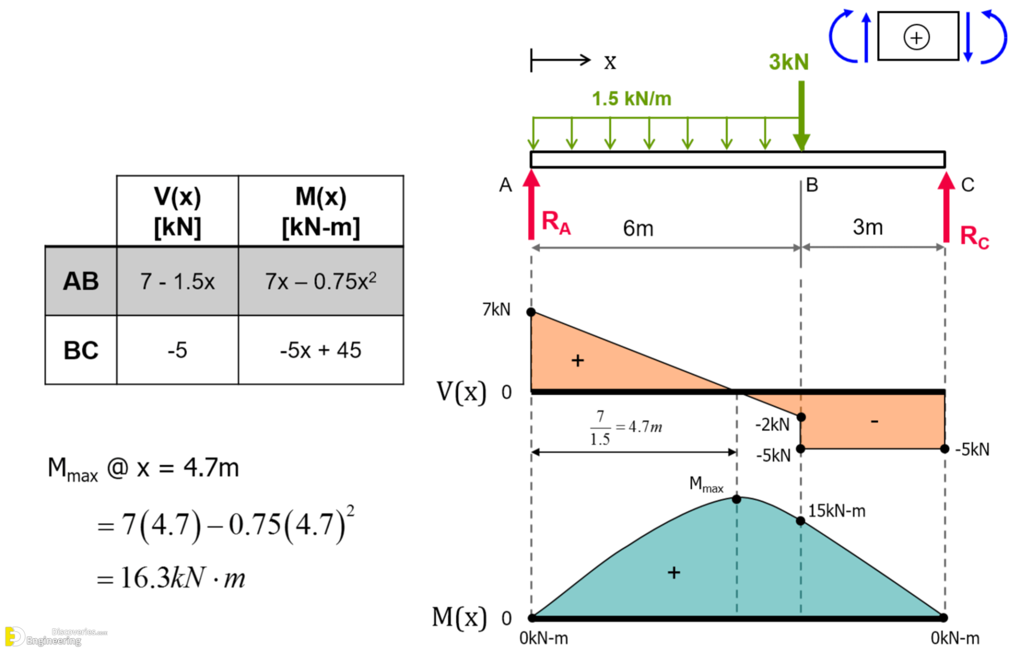
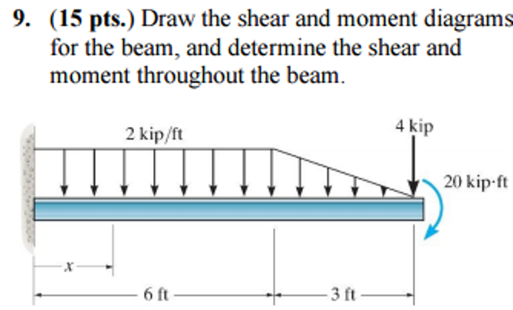
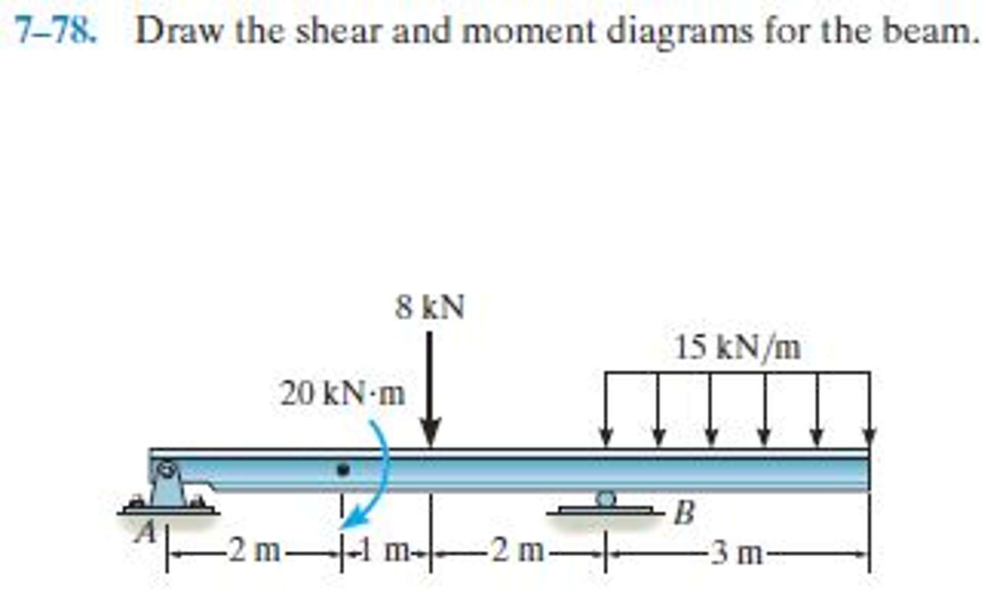
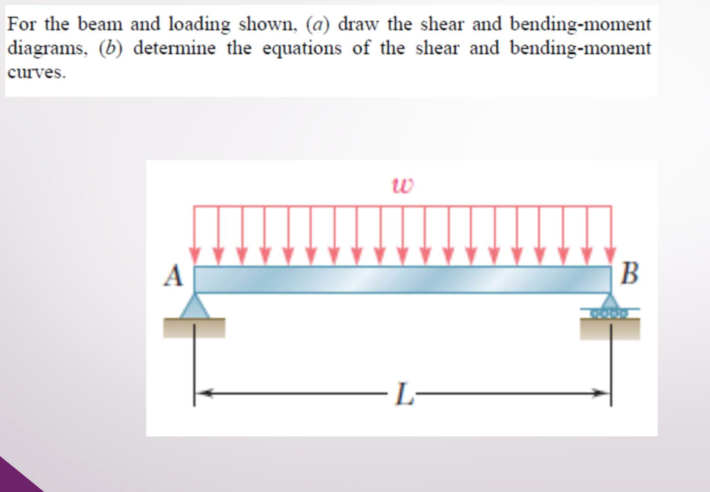
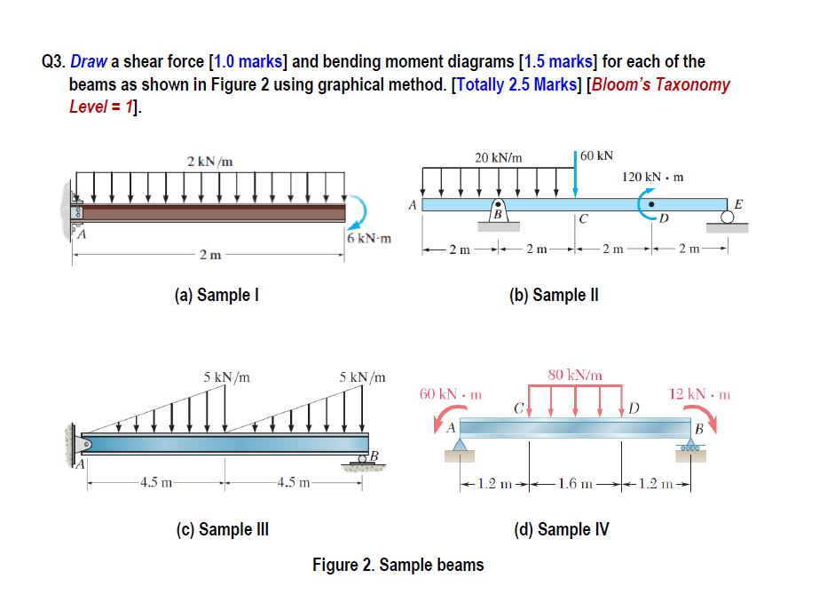
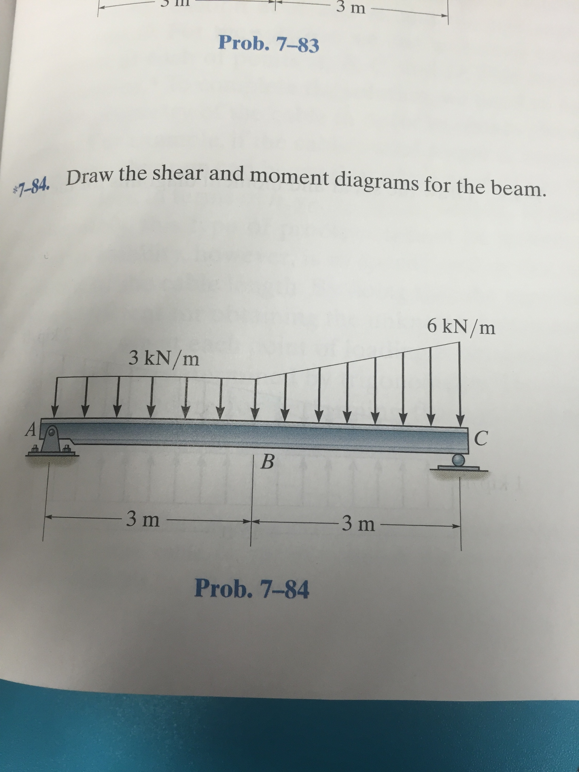
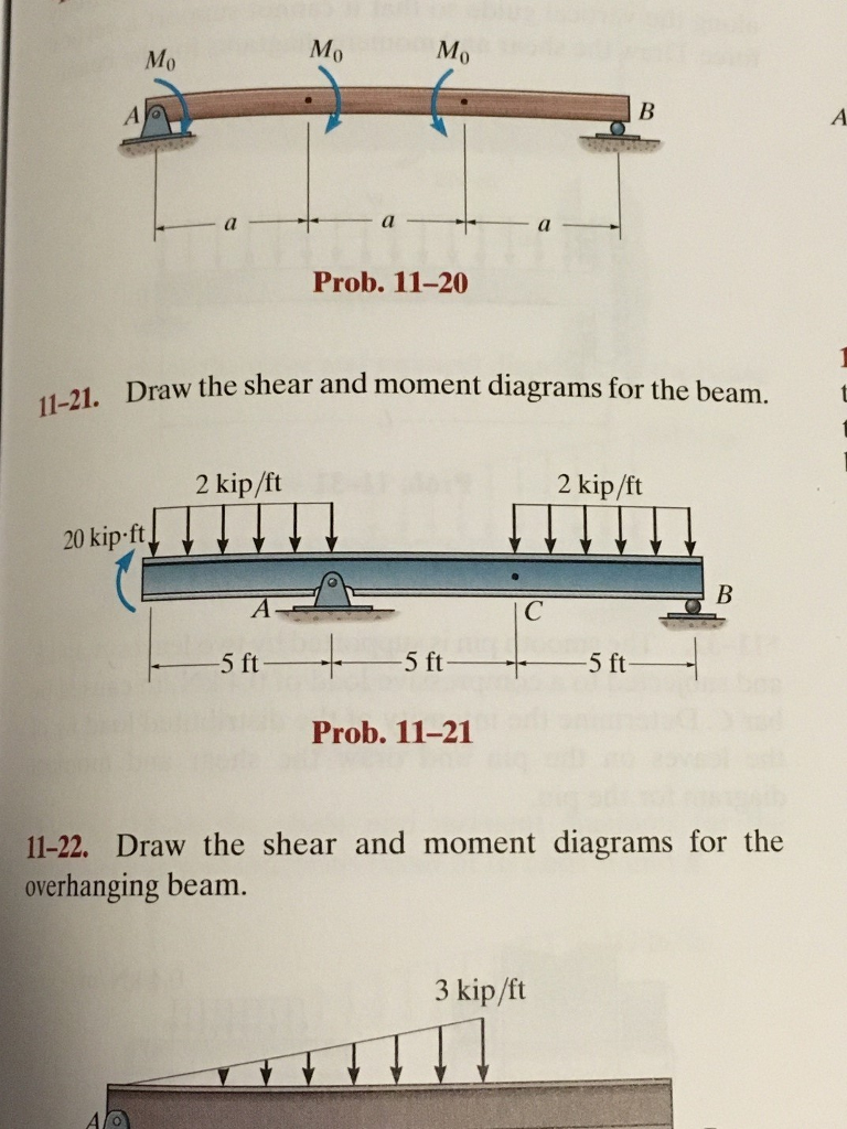
759 Draw The Shear And Moment Diagrams For The Beam - The distance x is measured from point a to the. Web draw the shear and moment diagrams for the beam. Web figures 1 through 32 provide a series of shear and moment diagrams with accompanying formulas for design of beams under various static loading conditions. Draw the shear and moment diagrams for the beam. Give numerical values at all change of. Include in your solution the equations for shear and moment for this beam for section ab. This page will walk you. Web draw the shear and moment diagrams for the beam. Web drawing shear force and bending moment diagrams: Web draw the shear force and bending moment diagrams for the cantilever beam supporting a concentrated load of 5 lb at the free end 3 ft from the wall. They allow us to see where the maximum. Divide the beam (of length l) into n segments. Shear force and bending moment are examples of interanl forces that are induced in a structure when loads are. Web without writing shear and moment equations, draw the shear and moment diagrams for the beams specified in the following problems. Web the first step in calculating these quantities and their spatial variation consists of constructing shear and bending moment diagrams, \(v(x)\) and \(m(x)\), which are. Free body diagram of the beam ( uvl height h = 30 ( l b f t) and moment m = 180 ( l b − f. Web write shear and moment equations for the beams in the following problems. 100% (2 ratings) share share. 30 lb/ft 180 lb ft 3. Web our calculator generates the reactions, shear force diagrams (sfd), bending moment diagrams (bmd), deflection, and stress of a cantilever beam or simply supported beam. Shear and bending moment equations. After you have the diagrams, answer the questions. Web the first step in calculating these quantities and their spatial variation consists of constructing shear and bending moment diagrams, \(v(x)\) and \(m(x)\), which are. Web draw the shear and moment diagrams for the beam. They allow us to see where the maximum. In each problem, let x be the distance measured from left end of the beam. Include in your solution the equations for shear and moment for this beam for section ab. Web draw the shear force and bending moment diagrams for the cantilever beam supporting a concentrated load of 5 lb at the free end 3 ft from the wall. The distance x is measured from point a to the. Free body diagram of the beam ( uvl height h = 30 ( l b f t) and moment m = 180 ( l b − f. Web draw the shear and moment diagrams for the beam. After you have the diagrams, answer the questions. Free body diagram of the beam ( uvl height h = 30 ( l b f t) and moment m = 180 ( l b − f. Web drawing shear force and bending moment diagrams: This page will walk you. Web understanding shear force and bending moment diagrams. In each problem, let x be the distance measured from left end of the beam. The distance x is measured from point a to the. Web drawing shear force and bending moment diagrams: Web the shear diagram will plot out the internal shearing forces within a beam, or other body that is. Divide the beam (of length l) into n segments. Include in your solution the equations for shear and moment for this beam for section ab. Free body diagram of the beam ( uvl height h = 30 ( l b f t) and moment m = 180 ( l b − f. Web write shear and moment equations for the. Web without writing shear and moment equations, draw the shear and moment diagrams for the beams specified in the following problems. Web write shear and moment equations for the beams in the following problems. 100% (2 ratings) share share. Web draw the shear force and bending moment diagrams for the cantilever beam supporting a concentrated load of 5 lb at. Shear and bending moment equations. This page will walk you. Web there are 3 steps to solve this one. Divide the beam (of length l) into n segments. Web the first step in calculating these quantities and their spatial variation consists of constructing shear and bending moment diagrams, \(v(x)\) and \(m(x)\), which are. The shear load and bending moment diagrams are constructed by integrating the distributed load to get the shear. Draw the shear and moment diagrams for the beam shown. To draw the shear diagram, we need to determine the shear force at different points along the beam. Web there are 3 steps to solve this one. Include in your solution the. Here’s the best way to solve it. Web draw the shear and moment diagrams for the beam. Shear and bending moment equations. This page will walk you. They allow us to see where the maximum. Web write shear and moment equations for the beams in the following problems. In each problem, let x be the distance measured from left end of the beam. Determine all the reactions on the beam. Web shear force and bending moment diagrams are powerful graphical methods that are used to analyze a beam under loading. The distance x is measured. Shear force and bending moment are examples of interanl forces that are induced in a structure when loads are. Web write shear and moment equations for the beams in the following problems. The distance x is measured from point a to the. Include in your solution the equations for shear and moment for this beam for section ab. Web understanding. After you have the diagrams, answer the questions. Web draw the shear and moment diagrams for the beam. Web the first step in calculating these quantities and their spatial variation consists of constructing shear and bending moment diagrams, \(v(x)\) and \(m(x)\), which are. Divide the beam (of length l) into n segments. 30 lb/ft 180 lb ft 3. Here’s the best way to solve it. Web shear force and bending moment diagrams are powerful graphical methods that are used to analyze a beam under loading. Web write shear and moment equations for the beams in the following problems. Shear force and bending moment are examples of interanl forces that are induced in a structure when loads are. Shear and bending moment equations. Web draw the shear and moment diagrams for the beam. To draw the shear diagram, we need to determine the shear force at different points along the beam. Web there are 3 steps to solve this one. Web understanding shear force and bending moment diagrams. Web drawing shear force and bending moment diagrams: The shear load and bending moment diagrams are constructed by integrating the distributed load to get the shear. The distance x is measured from point a to the. In each problem, let x be the distance measured from left end of the beam. This page will walk you. Web the shear diagram will plot out the internal shearing forces within a beam, or other body that is supporting multiple forces perpendicular to the length of the beam or body itself. They allow us to see where the maximum.Learn How To Draw Shear Force And Bending Moment Diagrams Engineering
Shear And Moment Diagrams For Beams
Draw the shear and moment diagrams for the beam. YouTube
Draw the shear and moment diagrams for the beam.
Beam Shear And Moment Diagrams
Shear and moment diagrams geekloki
Beam Shear And Moment Diagrams
Beam Shear And Moment Diagrams
draw the shear and moment diagrams for the beam chegg
Solved Draw the shear and moment diagrams for the beam
Web Without Writing Shear And Moment Equations, Draw The Shear And Moment Diagrams For The Beams Specified In The Following Problems.
Web Write Shear And Moment Equations For The Beams In The Following Problems.
Web Our Calculator Generates The Reactions, Shear Force Diagrams (Sfd), Bending Moment Diagrams (Bmd), Deflection, And Stress Of A Cantilever Beam Or Simply Supported Beam.
Web Figures 1 Through 32 Provide A Series Of Shear And Moment Diagrams With Accompanying Formulas For Design Of Beams Under Various Static Loading Conditions.
Related Post:
