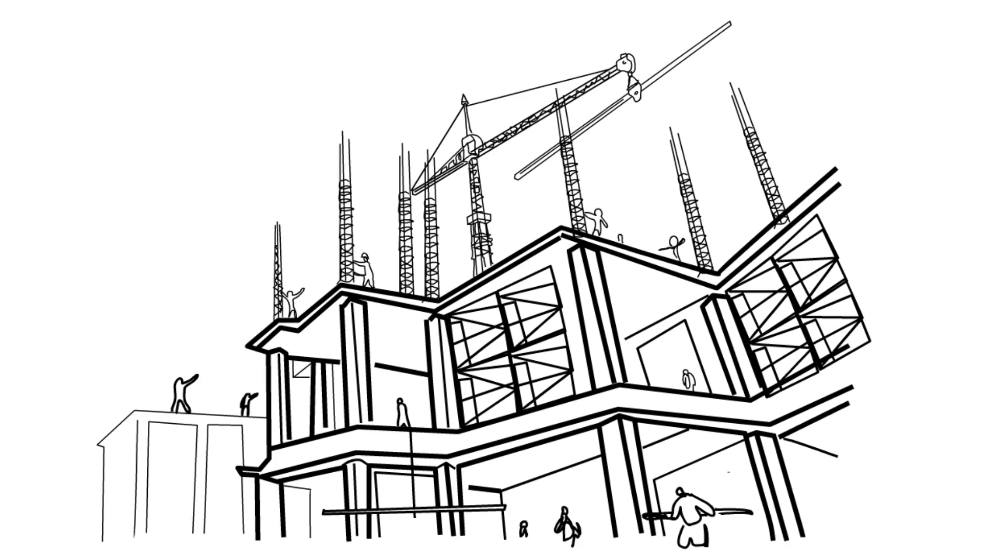
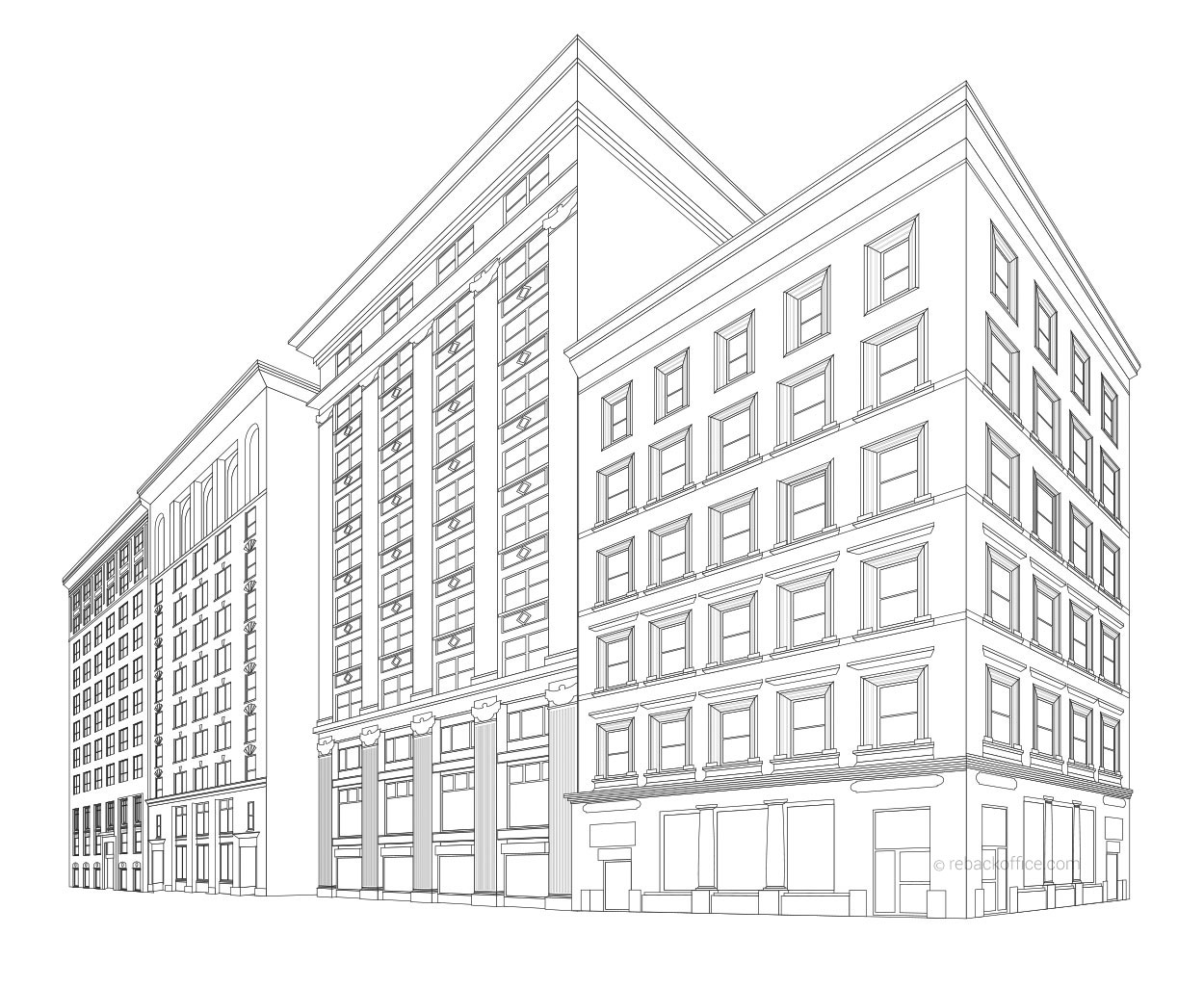
Construction Drawing Lines
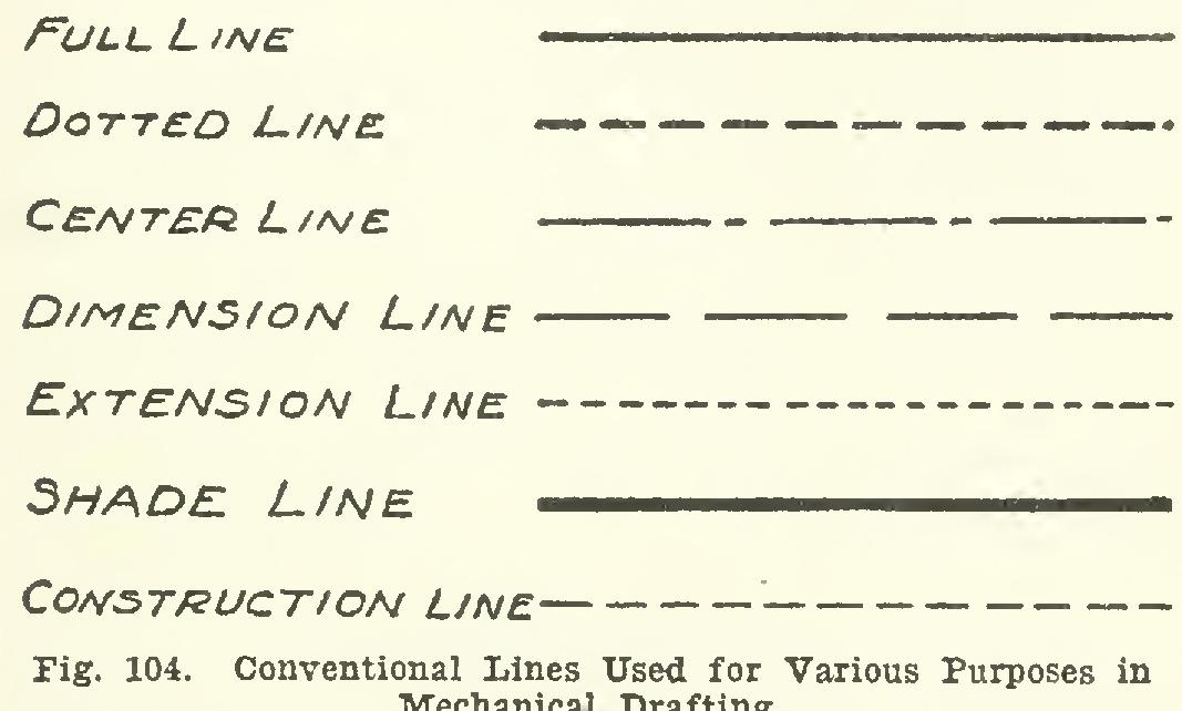
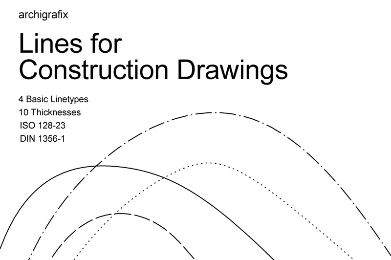
Construction Drawing Lines - The first and most basic rule of lines in design drawings is that solid lines indicate visible or “real” objects or surfaces, while anything drawing with dots and/or dashes indicates something that is unseen or “hidden” from view. The larger and more complex the project, the more drawings will be contained within. Web construction lines serve as the visual representation of a structure’s design. Web construction drawings, also known as plans or blueprints, are the heart and soul of any construction project. Web following are the different types of lines used in engineering drawing: Drawings of the whole house, or small details, may be at a different scale. Leader lines typically have an arrow at one end and a note for the drawing at the other end. The large blueprints or “working drawings” used on the job site are typically drawn at a scale of ¼” per foot. Imagine them as a detailed instruction manual that deciphers the complex language of. Web the magic of construction drawings lies in the details, components, and lines that convey vital information to the team. For example, with a construction drawing made at a scale of a quarter of an inch per foot, a drawn line measuring 1 inch equals 4 feet on the construction project. Web construction drawings form part of the overall documentation that is used for tender, for the contract between the employer and contractor, and for the construction itself. Long equals 4 ft., a line 4 in. Web the leader line can be a straight line or curved. The construction drawing provides a graphic representation of how the building will be built. Imagine them as a detailed instruction manual that deciphers the complex language of. They will be as clear as possible, and easy for the construction team to read. At a scale of ¼” per foot, a line 1 in. The large blueprints or “working drawings” used on the job site are typically drawn at a scale of ¼” per foot. Web draw electrical devices. Web draw electrical devices. Technical drawings like engineering and detail drawings unveil the. The tool is designed for cad style drawings but works just as well with any other type of modelling. Web the dotted lines in drawing files are called construction lines, and they are used to help draw complex shapes accurately by providing a reference point. For those in the field, understanding these symbols is not just a technical skill — it's an essential part of transforming the design on paper into a physical structure. Long equals 4 ft., a line 4 in. Web nearly all construction drawings are drawn to scale. This video explains what construction lines are, how to u. Web construction drawings, also known as plans or blueprints, are the heart and soul of any construction project. Reading a set of construction drawings requires that you learn basic drafting guidelines and the symbols that are used to convey meaning, much like a traffic sign tells you what to expect up ahead. They are usually temporary lines that are erased once the drawing is complete. Lock wrist and use arm to achieve straight line motion. For those in the field, understanding these symbols is not just a technical skill — it's an essential part of transforming the design on paper into a physical structure. Several types of leader lines are acceptable. Lines. Lines can represent different things depending on what “view” you. These drawings are a part of the information prepared by the design team in order to provide important instructions regarding the proposed building. Walk around your rooms and make note of where receptacles and switches are located on the wall, and where lights are on the ceiling. Reading a set. The first and most basic rule of lines in design drawings is that solid lines indicate visible or “real” objects or surfaces, while anything drawing with dots and/or dashes indicates something that is unseen or “hidden” from view. They enable architects and engineers to see the project before it becomes a reality. Once you have your blueprint, start marking where. Lock wrist and use arm to achieve straight line motion. Web the magic of construction drawings lies in the details, components, and lines that convey vital information to the team. Web solid versus dashed or dotted lines. Lines can represent different things depending on what “view” you. Web nearly all construction drawings are drawn to scale. Construction lines are meticulously drawn to exact measurements, ensuring the project’s accuracy. The tool is designed for cad style drawings but works just as well with any other type of modelling. In construction, precision is paramount. Build snappable guide points and guide edges, draw lines and primitive shapes in place, automatically create faces in closed geometry and precisely move object. For example, with a construction drawing made at a scale of a quarter of an inch per foot, a drawn line measuring 1 inch equals 4 feet on the construction project. For those in the field, understanding these symbols is not just a technical skill — it's an essential part of transforming the design on paper into a physical structure.. Web a construction drawing is an umbrella term for the technical drawings (usually a whole set of drawings) which provide graphic representation and guidelines for a project that is to be built. In construction, precision is paramount. Build snappable guide points and guide edges, draw lines and primitive shapes in place, automatically create faces in closed geometry and precisely move. Construction lines are meticulously drawn to exact measurements, ensuring the project’s accuracy. Lines can represent different things depending on what “view” you. These drawings are a part of the information prepared by the design team in order to provide important instructions regarding the proposed building. Web construction lines serve as the visual representation of a structure’s design. At a scale. They are usually temporary lines that are erased once the drawing is complete. For those in the field, understanding these symbols is not just a technical skill — it's an essential part of transforming the design on paper into a physical structure. Drawings of the whole house, or small details, may be at a different scale. Web construction drawings form. Leader lines typically have an arrow at one end and a note for the drawing at the other end. For example, with a construction drawing made at a scale of a quarter of an inch per foot, a drawn line measuring 1 inch equals 4 feet on the construction project. Web following are the different types of lines used in. Reading a set of construction drawings requires that you learn basic drafting guidelines and the symbols that are used to convey meaning, much like a traffic sign tells you what to expect up ahead. Walk around your rooms and make note of where receptacles and switches are located on the wall, and where lights are on the ceiling. They will be as clear as possible, and easy for the construction team to read. Web the leader line can be a straight line or curved. Web nearly all construction drawings are drawn to scale. The first and most basic rule of lines in design drawings is that solid lines indicate visible or “real” objects or surfaces, while anything drawing with dots and/or dashes indicates something that is unseen or “hidden” from view. These drawings are a part of the information prepared by the design team in order to provide important instructions regarding the proposed building. Lock wrist and use arm to achieve straight line motion. Web a construction drawing is an umbrella term for the technical drawings (usually a whole set of drawings) which provide graphic representation and guidelines for a project that is to be built. Technical drawings like engineering and detail drawings unveil the. Use of short and long break lines in structural drawings. Web following are the different types of lines used in engineering drawing: Drawings of the whole house, or small details, may be at a different scale. The leader is a thin dark line (see figure 1). Construction lines are meticulously drawn to exact measurements, ensuring the project’s accuracy. Lines can represent different things depending on what “view” you.Building Construction Sketch at Explore collection
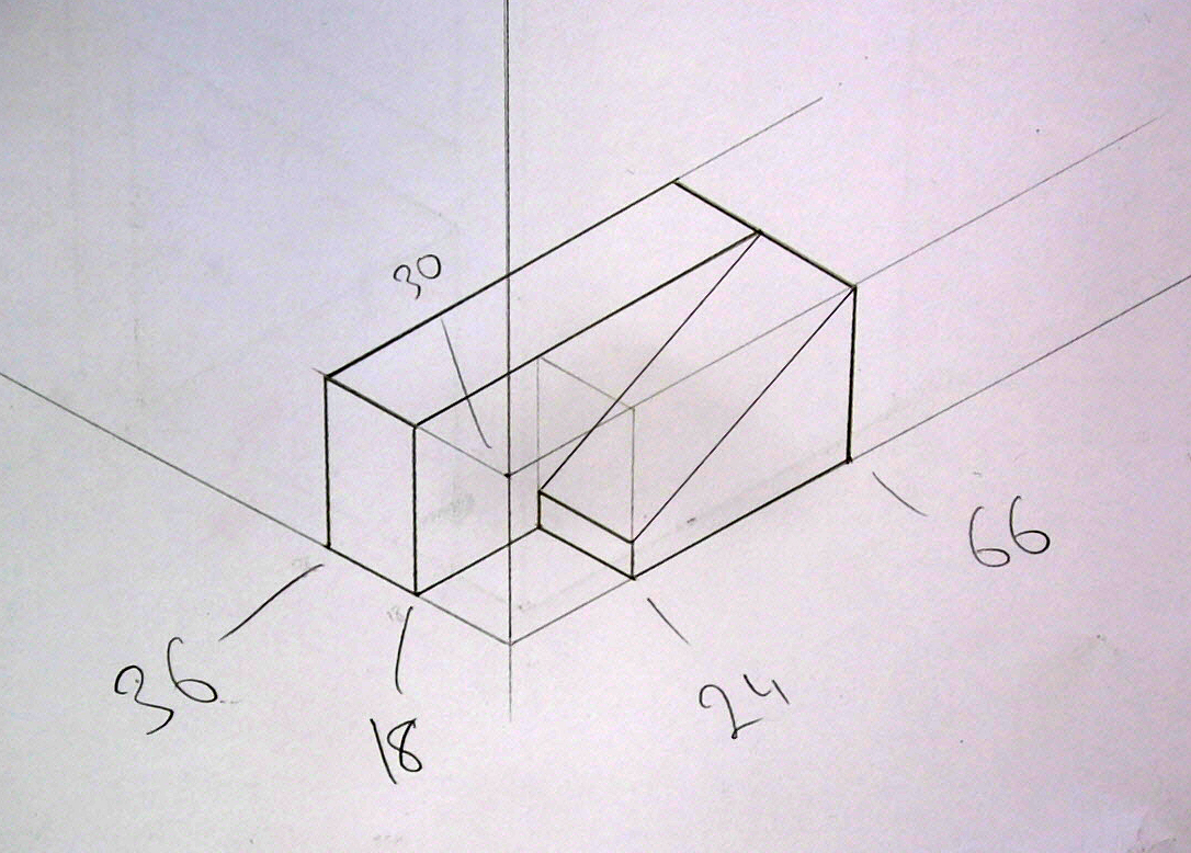
Construction Line Drawing at Explore collection of
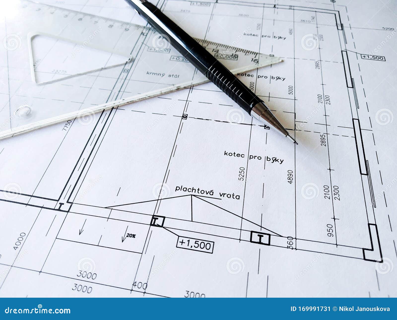
Construction Drawing Architecture Detail White Paper with Dimensions
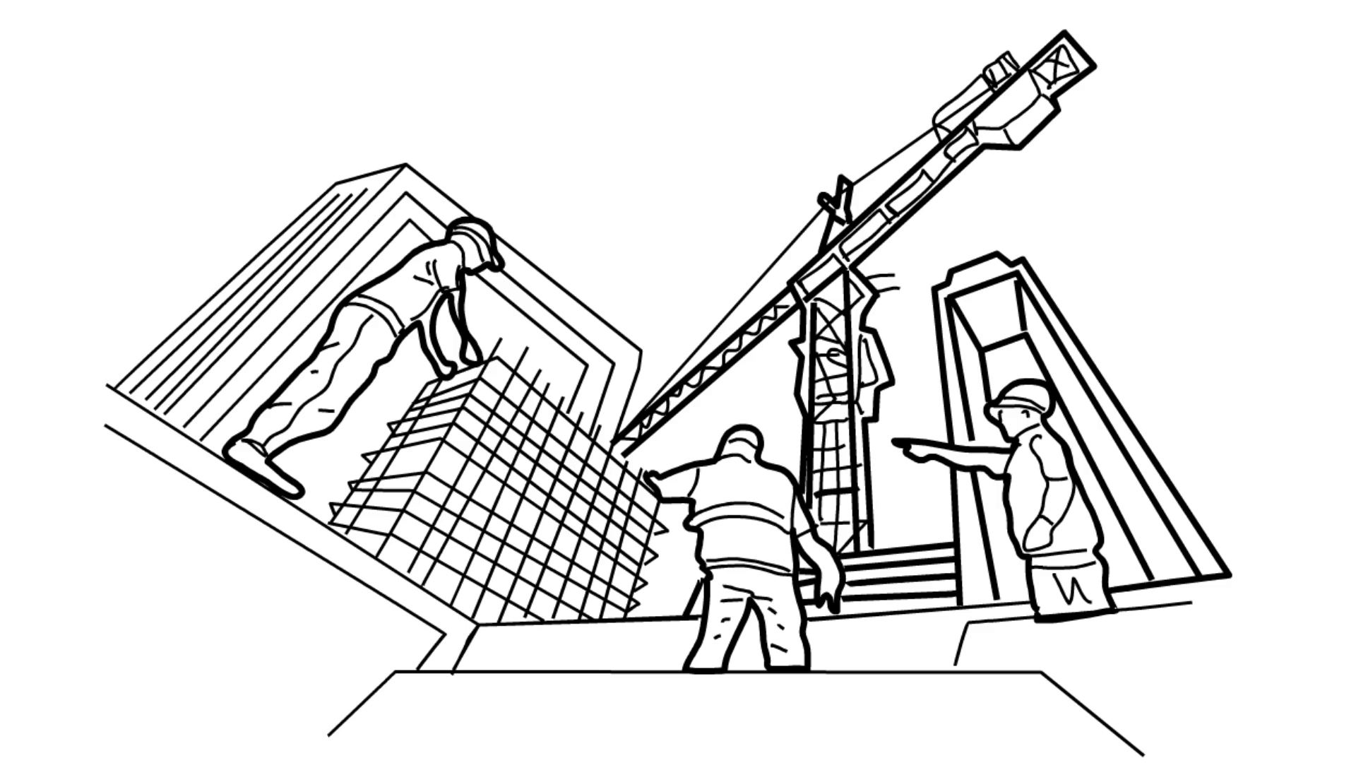
Free Construction Drawings at Explore collection
Construction Line Drawing at Explore collection of
construction line drawing sketch Ardelle Irving
Construction Line Drawing at Explore collection of
Construction Drawing Lines
Create High Quality Construction Drawings with ISO Standard Revit
Building Line Drawing at GetDrawings Free download
Construction Lines Help Determine The Correct Size And Scale Of Objects Within A Drawing.by Defining The Overall Dimensions And Relative Positions Of Various Elements, Construction Lines Ensure That The Final Illustration Accurately Represents The Intended Design.
At A Scale Of ¼” Per Foot, A Line 1 In.
The Large Blueprints Or “Working Drawings” Used On The Job Site Are Typically Drawn At A Scale Of ¼” Per Foot.
They Hold The Key To Understanding The Design, Dimensions, Materials, And Methods Required To Transform An Idea Into A Physical Structure.
Related Post:
