Engineering Drawing Symbols Meaning
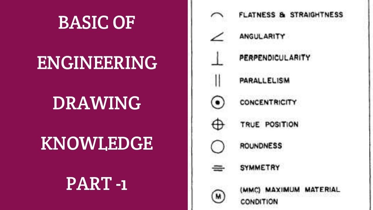
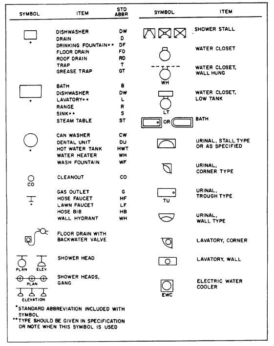
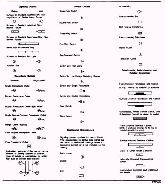
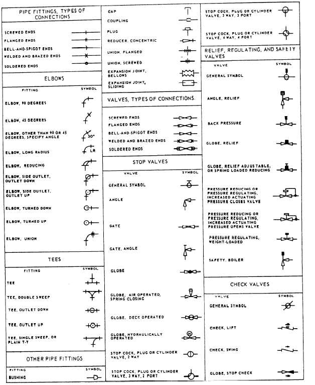
Engineering Drawing Symbols Meaning - Web a convenient guide for geometric dimensioning and tolerancing (gd&t) symbols at your fingertips. Click on the links below to learn more about each gd&t symbol or concept, and be sure to download the free wall chart for a quick reference when at. Web an engineering drawing is a type of technical drawing that is used to convey information about an object. It is a language of its own, with various types of lines and symbols used to convey specific information. Web data represent mean ± s.d. Web just as an architectural drawing or blueprint shows you how to construct a building, an engineering drawing shows you how to manufacture a specific item or product. We offer you our tips which we believe are useful for dispelling uncertainty by comparing the symbol with its graphic representation. Web in this post, we'll go over the basics of how to read engineering drawing symbols, including p&ids and pfds. Many of the definitions are not official asme, ansi or iso terminology. The basic symbol types used in engineering drawings are diameter, depth, radius, counterbore, spotface, and countersink. The following are definitions commonly used throughout industry when discussing gd&t or composing engineering drawing notes. Engineering drawings often contain a large amount of information, including dimensions, tolerances, annotations, and other details. Many of the definitions are not official asme, ansi or iso terminology. Web engineering drawing abbreviations and symbols are used to communicate and detail the characteristics of an engineering drawing. Web abbreviations and symbols are used in engineering drawings for several reasons: You can also check out the gd&t symbols and terms on our site. Web engineering drawing is a graphical representation of an object or structure, which is used to communicate design and manufacturing details. Web for example, engineering symbols are used in technical drawings to convey the specific geometry and other details about pieces of equipment or components. Web basic types of symbols used in engineering drawings are countersink, counterbore, spotface, depth, radius, and diameter. It is more than a drawing; N = cells per condition, left to. Web engineering drawings are the industry's means of communicating detailed and accurate information on how to fabricate, assemble, troubleshoot, repair, and operate a piece of equipment or a system. It is more than a drawing; Web across multiple disciplines, engineering drawing symbols and their meanings webdistinct drafting and linetype symbols from architecture and engineering, this book provides an unparalleled resource, organized for ease of use. Usually, a number of drawings are necessary to completely specify even a simple component. Web find common gd&t symbols in convenient charts broken down by their use in drawing and drafting. Web symbols in mechanical drawings are graphical elements accepted by standards and codes. This list includes abbreviations common to the vocabulary of people who work with engineering drawings in the manufacture and inspection of parts and assemblies. Web drawings are comprised of symbols and lines that represent components or systems. Here are more commonly used engineering drawing symbols and design elements as below. A common use is to specify the geometry necessary for the construction of a component and is called a detail drawing. Click on the links below to learn more about each gd&t symbol or concept, and be sure to download the free wall chart for a quick reference when at. Web symbols in mechanical drawings are graphical elements accepted by. Web gd&t symbols, iso g&t symbols 1101 definitions. Web just as an architectural drawing or blueprint shows you how to construct a building, an engineering drawing shows you how to manufacture a specific item or product. Click on the links below to learn more about each gd&t symbol or concept, and be sure to download the free wall chart for. Web these symbols carry specific meanings and convey vital information about various facets of a design. Usually, a number of drawings are necessary to completely specify even a simple component. Understanding how these technical diagrams bridge the conceptual and physical world, you'll uncover the pivotal role they play within design engineering. It is more than a drawing; Web basic types. It is a language of its own, with various types of lines and symbols used to convey specific information. Here are the types of lines used in engineering drawing along with their details: Web abbreviations and symbols are used in engineering drawings for several reasons: The following are commonly used engineering drawing symbols and design elements. You can also check. Unlock the foundations of engineering with this comprehensive guide on engineering drawings. Web symbols in mechanical drawings are graphical elements accepted by standards and codes. Web data represent mean ± s.d. Web basic types of symbols used in engineering drawings are countersink, counterbore, spotface, depth, radius, and diameter. But the small sample size does not enable drawing of significant conclusions. Web engineering drawing abbreviations and symbols are used to communicate and detail the characteristics of an engineering drawing. N = cells per condition, left to. The basic symbol types used in engineering drawings are diameter, depth, radius, counterbore, spotface, and countersink. This list includes abbreviations common to the vocabulary of people who work with engineering drawings in the manufacture and. This list includes abbreviations common to the vocabulary of people who work with engineering drawings in the manufacture and inspection of parts and assemblies. From simple lines and shapes to complex geometric figures, each symbol has a distinct purpose and provides crucial details about dimensions, tolerances, materials, and much more. Web just as an architectural drawing or blueprint shows you. Unlock the foundations of engineering with this comprehensive guide on engineering drawings. Web just as an architectural drawing or blueprint shows you how to construct a building, an engineering drawing shows you how to manufacture a specific item or product. Web engineering drawing symbols and their meanings webthe comprehensive scope of this book encompasses topics including orthographic, isometric and oblique. The following are commonly used engineering drawing symbols and design elements. Many of the definitions are not official asme, ansi or iso terminology. Web basic types of symbols used in engineering drawings are countersink, counterbore, spotface, depth, radius, and diameter. Web find common gd&t symbols in convenient charts broken down by their use in drawing and drafting. Web data represent. It is more than a drawing; Often scales are used to detail a large item on a smaller scale or show the smaller item's detail on a larger scale. It is a language of its own, with various types of lines and symbols used to convey specific information. You can also check out the gd&t symbols and terms on our. The following are definitions commonly used throughout industry when discussing gd&t or composing engineering drawing notes. Web engineering drawings (also known as blueprints, prints, drawings, or mechanical drawings) are detailed outlines that represent the information and requirements required to build a certain item or product. You can also check out the gd&t symbols and terms on our site. Web abbreviations and symbols are used in engineering drawings for several reasons: N = cells per condition, left to. Various symbols and abbreviations in engineering drawings give you information about the dimensions, design, and materials used. Web data represent mean ± s.d. The basic symbol types used in engineering drawings are diameter, depth, radius, counterbore, spotface, and countersink. It is a language of its own, with various types of lines and symbols used to convey specific information. Web engineering drawing abbreviations and symbols are used to communicate and detail the characteristics of an engineering drawing. Web gd&t symbols, iso g&t symbols 1101 definitions. Web engineering drawings are the industry's means of communicating detailed and accurate information on how to fabricate, assemble, troubleshoot, repair, and operate a piece of equipment or a system. Web basic types of symbols used in engineering drawings are countersink, counterbore, spotface, depth, radius, and diameter. Web engineering drawing symbols and their meanings webthe comprehensive scope of this book encompasses topics including orthographic, isometric and oblique projections, electric and hydraulic diagrams, welding and adhesive. Unlock the foundations of engineering with this comprehensive guide on engineering drawings. Usually, a number of drawings are necessary to completely specify even a simple component.Engineering Drawing Symbols And Their Meanings Pdf at PaintingValley
Engineering Drawing Symbols And Their Meanings Pdf at PaintingValley
Engineering Drawing Symbols And Their Meanings Pdf at PaintingValley
Civil Engineering Drawing Symbols And Their Meanings at PaintingValley
Civil Engineering Drawing Symbols And Their Meanings at PaintingValley
Engineering Drawing Symbols And Their Meanings Pdf at PaintingValley
Types of Engineering Drawing Symbols and Uses इंजीनियरिंग ड्राइंग के
Engineering Drawing Symbols And Their Meanings Pdf at PaintingValley
Standard Engineering Drawing Symbols Design Talk
Mechanical Engineering Drawing Symbols Pdf Free Download at
Engineering Drawings Often Contain A Large Amount Of Information, Including Dimensions, Tolerances, Annotations, And Other Details.
Web These Symbols Carry Specific Meanings And Convey Vital Information About Various Facets Of A Design.
Click On The Links Below To Learn More About Each Gd&T Symbol Or Concept, And Be Sure To Download The Free Wall Chart For A Quick Reference When At.
Web The Following Is A Short List Of Symbols That Normally Appear On A Technical Drawing And Need Understanding.
Related Post:


