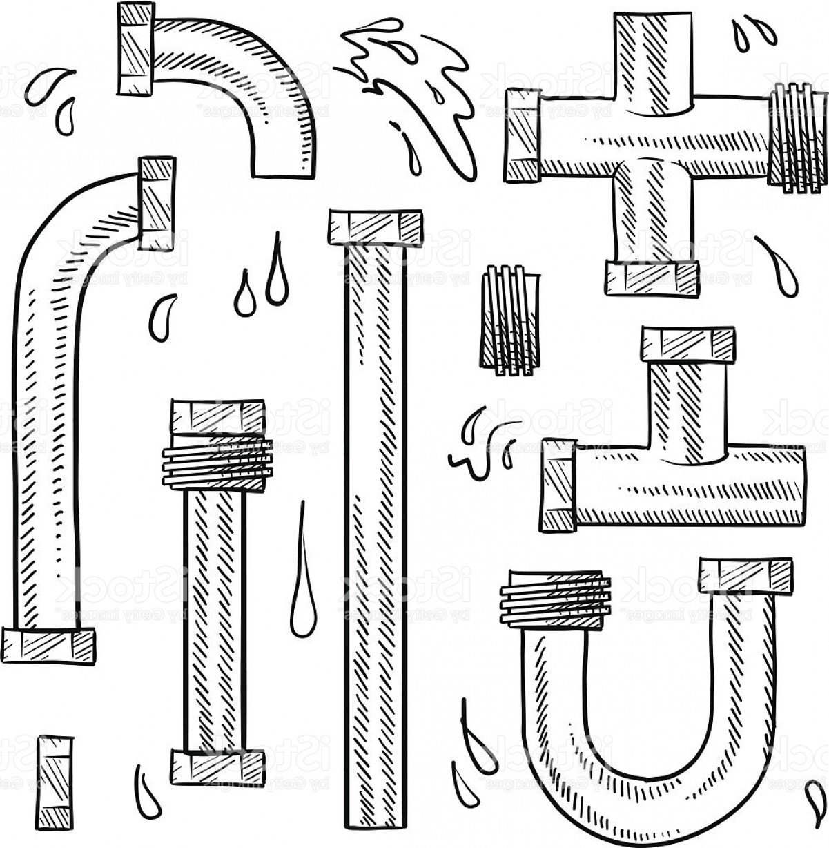
Pipework Drawings
Pipework Drawings - Access to a comprehensive library of piping symbols is crucial and includes various fitting types and connections. These drawings are schematic representations and they would define functional relationships in a piping system. Web the features of edrawmax. These tools generate the 3d representation of the piping layout, including pipe dimensions, fittings,. Web piping isometric drawing is an isometric representation of single pipe line in a plant. Piping fabrication work is based on isometric drawings. Create cad drawings for engineering and scaled plans online with smartdraw. It is the most important deliverable of piping engineering department. So engineers and designers must be aware of the isometric preparation steps. Web a piping isometric drawing is a technical illustration that presents a 3d representation of a piping system. Edrawmax is ideal for pip design engineers and design designers who must draw detailed pip design drawings. Cad software with piping tools preinstalled. Web a piping system drawing may be represented by the following three methods. Reading tips, symbols, and drawing techniques for engineers and piping professionals. Process flow diagram (pfd) piping and instrumentation drawing (p&id) plot. Browse piping diagram templates and examples you can make with smartdraw. Piping fabrication work is based on isometric drawings. General arrangement drawing (gad)/piping plan drawing. Many abbreviations are common and are regularly used in the drawings but few of the abbreviation are new and unique for a particular drawing. Web piping isometric drawing software is an essential tool for piping engineers and designers to create detailed isometric drawings of piping systems. Edrawmax is ideal for pip design engineers and design designers who must draw detailed pip design drawings. Create cad drawings for engineering and scaled plans online with smartdraw. It is the most important deliverable of any project where piping plays a vital role. Web piping isometric is a representation of a single pipe line in a process plant with exact dimensions and bill of material (bom). Web various symbols are used to indicate piping components, instrumentation, equipments in engineering drawings such as piping and instrumentation diagram (p&id), isometric drawings, plot plan, equipment layout, welding drawings etc. It is used by the fabricator in fabricating the line. In very complex or large piping systems, piping isometrics are essential to the design and manufacturing phases of a project. Web piping drawings are basically the schematic representations that define functional relationships in a piping or pipeline system. It is used by the piping material group in purchasing the material for the line. Web an isometric drawing (or “iso”) is a pictorial view of one pipe, using isometric projection conventions to present a 2d view of a 3d pipe (fig. In very complex or large piping systems, piping isometrics are essential to the design and manufacturing phases of a project. These highly structured drawings provide a comprehensive 3d representation of the arrangement, dimensions, and connections of pipes within a system. Web master piping isometrics with our comprehensive guide: Web the main purpose of a piping drawing is to communicate the. Piping fabrication work is based on isometric drawings. Reading tips, symbols, and drawing techniques for engineers and piping professionals. The drawing sheet sizes shall be any of the following. Access to a comprehensive library of piping symbols is crucial and includes various fitting types and connections. These schemes contain numerous symbols, symbols, and abbreviations representing numerous components, such as pipes,. Process flow diagram (pfd) piping and instrumentation drawing (p&id) plot. Whenever you start reading a piping drawing or document, you can see many abbreviations on these drawings/documents. Web in this article, we will explore all those piping drawings that are required to execute piping work. Reading tips, symbols, and drawing techniques for engineers and piping professionals. General arrangement drawing (gad)/piping. Piping isometric drawing consists of three sections. There are usually five types of piping drawings that are prepared to communicate various information in a simple and easy way. In very complex or large piping systems, piping isometrics are essential to the design and manufacturing phases of a project. It is the most important deliverable of piping engineering department. Browse piping. Web a piping system drawing may be represented by the following three methods. Web an isometric drawing (or “iso”) is a pictorial view of one pipe, using isometric projection conventions to present a 2d view of a 3d pipe (fig. Web piping isometric drawing software is an essential tool for piping engineers and designers to create detailed isometric drawings of. Web an isometric drawing (or “iso”) is a pictorial view of one pipe, using isometric projection conventions to present a 2d view of a 3d pipe (fig. It is the most important deliverable of any project where piping plays a vital role. Create cad drawings for engineering and scaled plans online with smartdraw. Web piping isometric drawing is an isometric. Web piping isometric drawing software is an essential tool for piping engineers and designers to create detailed isometric drawings of piping systems. Web a piping isometric drawing is a technical illustration that presents a 3d representation of a piping system. In very complex or large piping systems, piping isometrics are essential to the design and manufacturing phases of a project.. Piping isometric drawing consists of three sections. Whenever you start reading a piping drawing or document, you can see many abbreviations on these drawings/documents. Web various symbols are used to indicate piping components, instrumentation, equipments in engineering drawings such as piping and instrumentation diagram (p&id), isometric drawings, plot plan, equipment layout, welding drawings etc. The drawing axes of the isometrics. The drawing axes of the isometrics intersect at an angle of 60°. It is used by the fabricator in fabricating the line. Whenever you start reading a piping drawing or document, you can see many abbreviations on these drawings/documents. The iso shows routing and dimension lines of the piping only. These schemes contain numerous symbols, symbols, and abbreviations representing numerous. Web a piping system drawing may be represented by the following three methods. Web the features of edrawmax. Web piping drawings are basically the schematic representations that define functional relationships in a piping or pipeline system. Create cad drawings for engineering and scaled plans online with smartdraw. Many abbreviations are common and are regularly used in the drawings but few. Web in this article, we will explore all those piping drawings that are required to execute piping work. The drawings would help to speed up the fabrication and erection work at the site. So engineers and designers must be aware of the isometric preparation steps. Unlike orthographic drawings that show different views (front, side, and top) separately, isometric drawings combine these views into a. Cad software with piping tools preinstalled. The drawing sheet sizes shall be any of the following. Web piping drawings are basically the schematic representations that define functional relationships in a piping or pipeline system. Web the main purpose of a piping drawing is to communicate the information in a simple way. Web master piping isometrics with our comprehensive guide: It is the most important deliverable of piping engineering department. The drawing axes of the isometrics intersect at an angle of 60°. These schemes contain numerous symbols, symbols, and abbreviations representing numerous components, such as pipes, valves, pumps, and. Access to a comprehensive library of piping symbols is crucial and includes various fitting types and connections. Process flow diagram (pfd) piping and instrumentation drawing (p&id) plot. Reading tips, symbols, and drawing techniques for engineers and piping professionals. It is the most important deliverable of any project where piping plays a vital role.How to read isometric drawing piping dadver
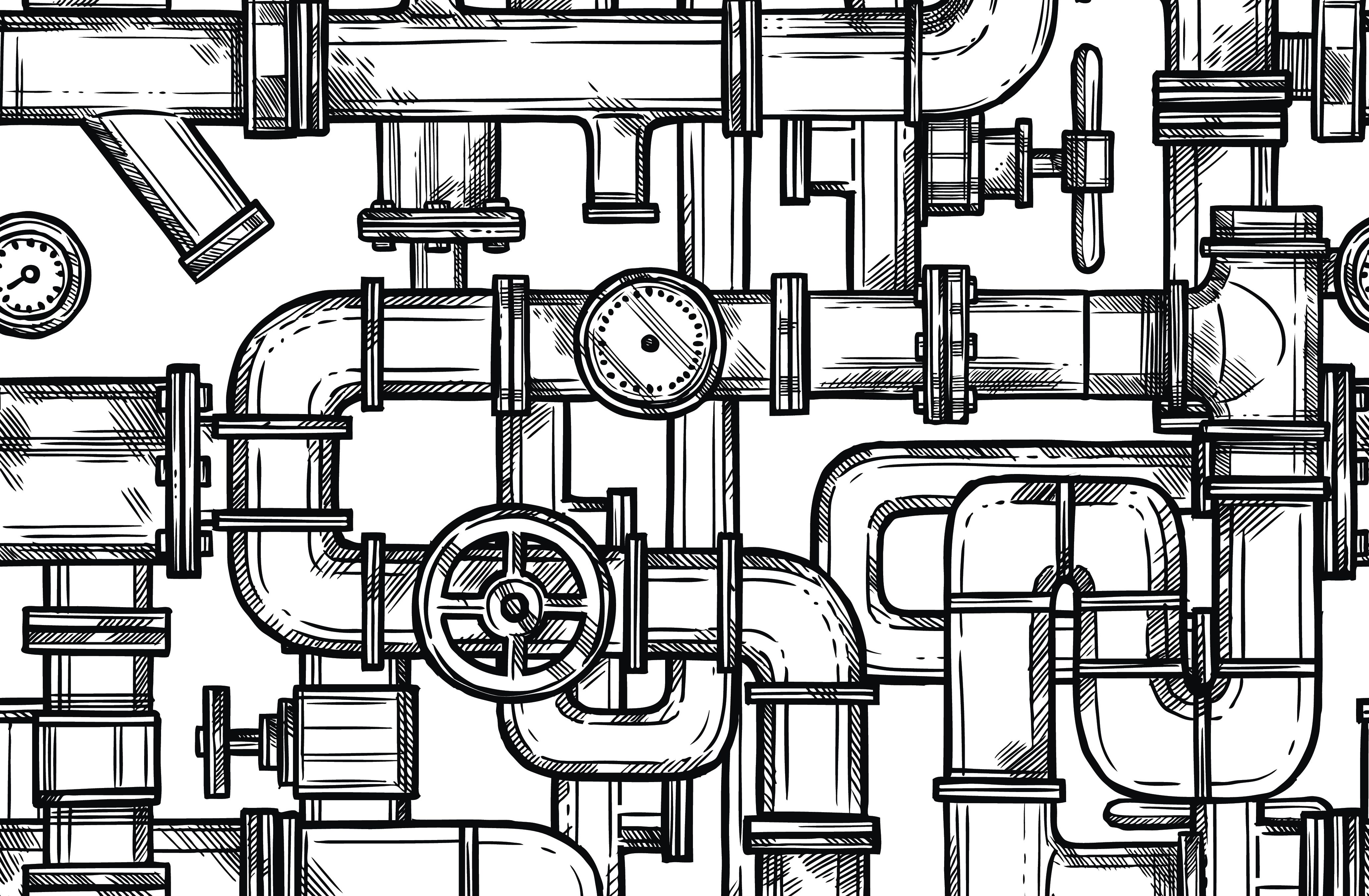
Pipes Drawing at GetDrawings Free download
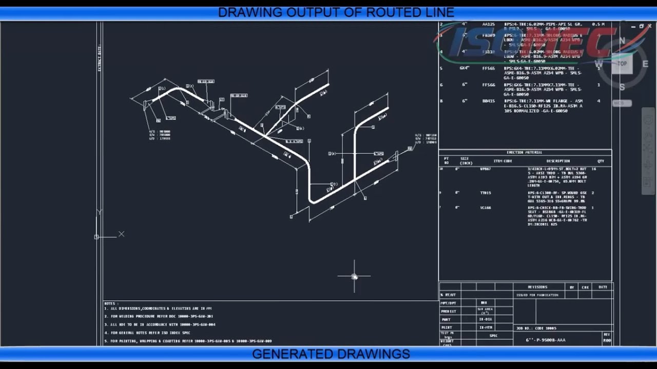
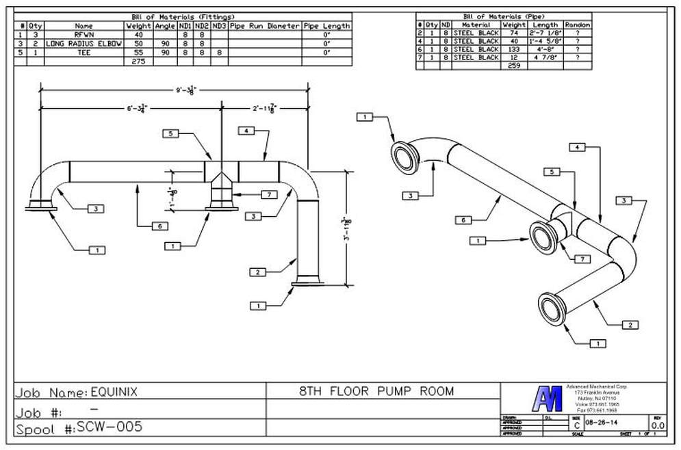
Piping Isometric Drawing at Explore collection of
How to read piping isometric drawing, Pipe fitter training, Watch the
How to Draw Isometric Pipe Drawings in Autocad Gautier Camonect
Isometric Piping Drawings Advenser
Sample isometric drawing for piping klowebcam
PIPING DRAWINGS
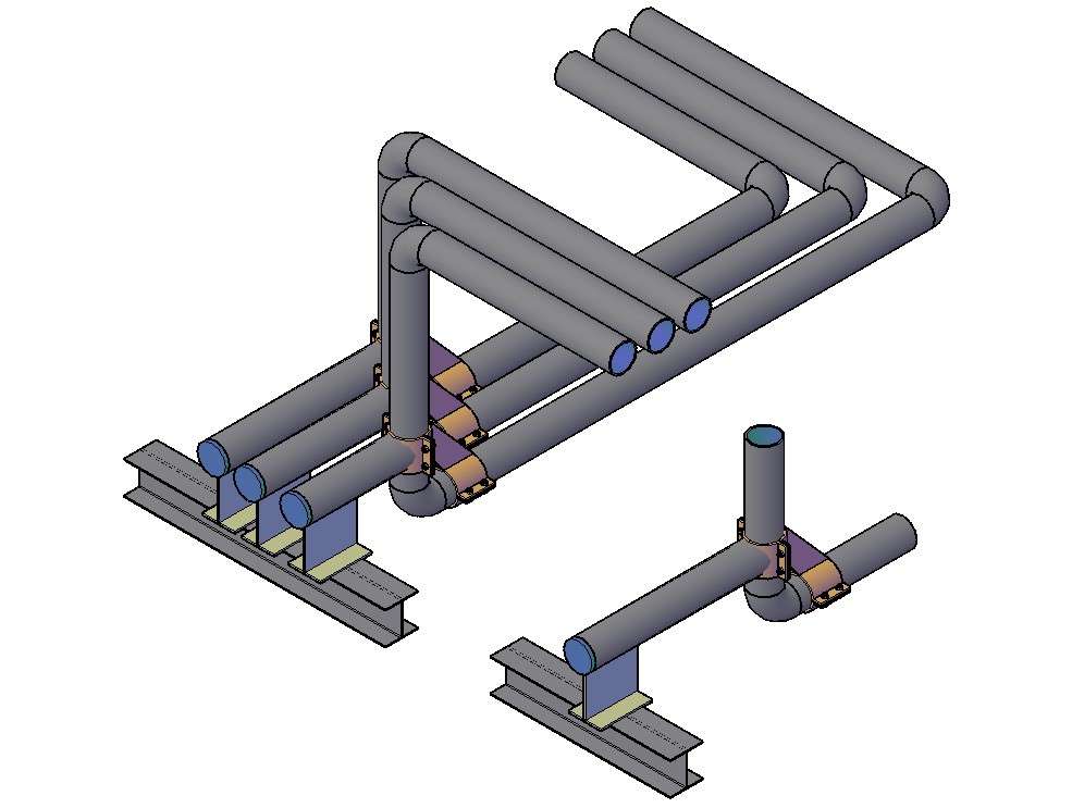
3D Pipe Drawing In AutoCAD File Cadbull
Pipe Sketch at Explore collection of Pipe Sketch
It Is Used By The Piping Material Group In Purchasing The Material For The Line.
Web Piping Isometric Drawing Is An Isometric Representation Of Single Pipe Line In A Plant.
These Highly Structured Drawings Provide A Comprehensive 3D Representation Of The Arrangement, Dimensions, And Connections Of Pipes Within A System.
These Tools Generate The 3D Representation Of The Piping Layout, Including Pipe Dimensions, Fittings,.
Related Post:

