Piping Drawing
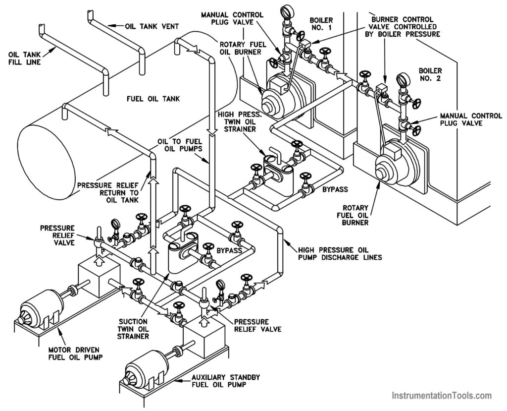
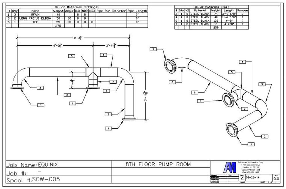
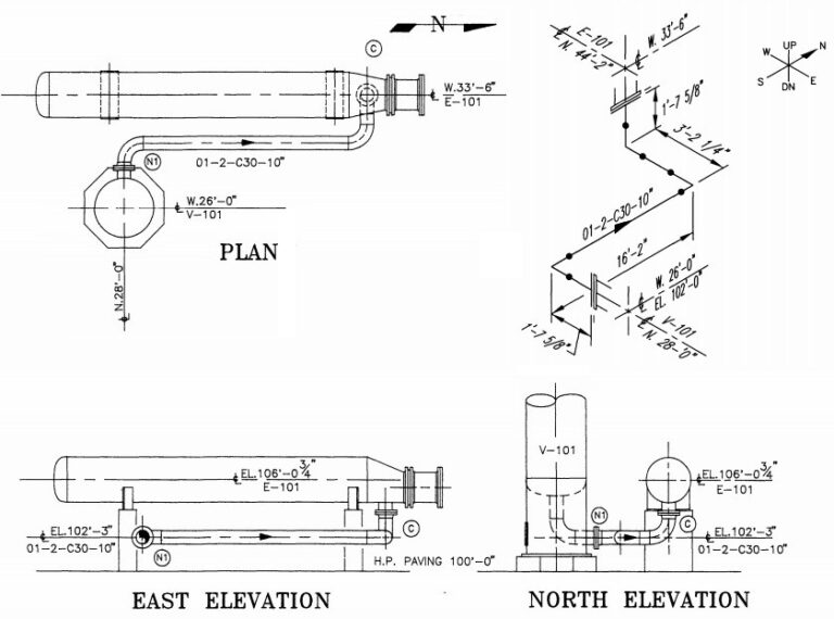
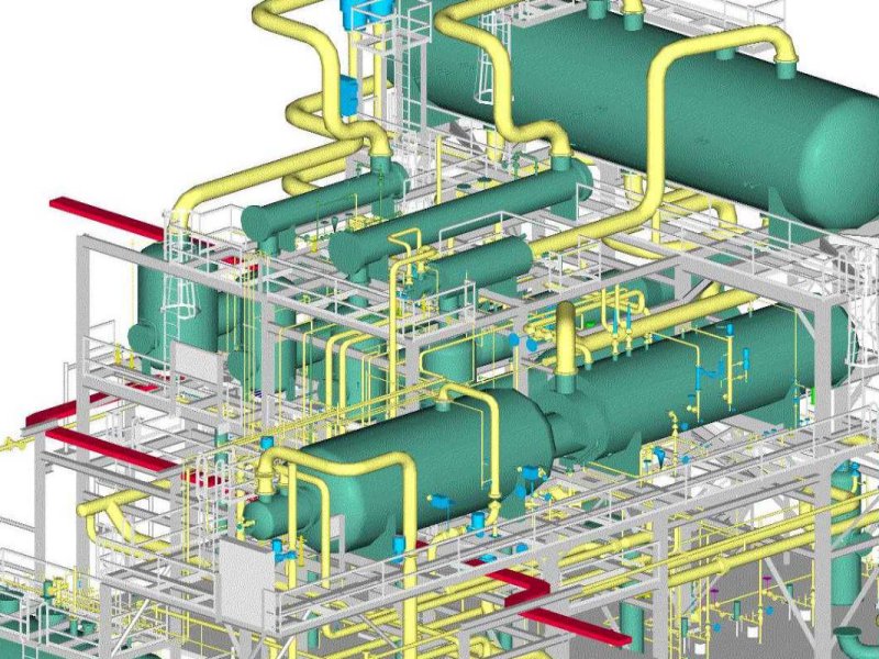
Piping Drawing - Web in this article, working on piping drawings is discussed closely including types of piping drawings and why they are vital. The basic elements of piping design. Web the 2024 olympics opening ceremony received rave reviews, with gojira, lady gaga and celine dion in particular drawing praise from critics. It is the most important deliverable of piping engineering department. How to draw piping in cad like a pro. It describes a quantity of energy. The drawing axes of the isometrics intersect at an angle of 60°. Piping fabrication work is based on isometric drawings. Piping joint types, weld types. Web explain the process of pipe identification. Charge is like the drops of water inside the pipe; Web engineering drawings are the industry’s means of communicating detailed and accurate information on how to fabricate, assemble, troubleshoot, repair, and operate a piece of equipment or a system. There are many piping isometric drawing software programs available. Piping joint types, weld types. Web piping and instrumentation diagrams (p&ids) are articulate drawings of a processing plan with various symbols and abbreviations that entail the piping and process equipment with its instrumentation and control machinery. We will explain electricity by drawing an analogy to water in a pipe. In other words, p&ids are schematics or diagrams that lay out the basics of a piping design for what will. Collect relevant information about the p&id diagram you will create and understand the process your drawing will represent. If you are in the oil and gas, chemical, or manufacturing industries, you probably are looking for a straightforward way to draw piping in cad. Web piping isometric drawing software is an essential tool for piping engineers and designers to create detailed isometric drawings of piping systems. Web piping drawings are basically the schematic representations that define functional relationships in a piping or pipeline system. Appreciate the various piping classes based on the design and application. Plumbing deals with piping in buildings which carry water, gas, and wastes in the industrial buildings. Determine what symbols you will need. The basic elements of piping design. Collect relevant information about the p&id diagram you will create and understand the process your drawing will represent. Web piping isometric drawings are rich in information about the various components and connections within a piping system. It’s comparable to the human body; Web a piping system drawing may be represented by the following three methods. Web piping and instrumentation diagrams (p&ids) are articulate drawings of a processing plan with various symbols and abbreviations that entail the piping and process equipment with its instrumentation and control machinery. Web the 2024 olympics opening ceremony received rave reviews, with gojira, lady gaga and celine dion in particular drawing praise from critics. It describes a quantity of energy. Web piping isometric drawing software is an essential tool for piping engineers and designers to create detailed isometric drawings of piping systems. In most cases, you will find that a plumbing plan. If you are in the oil and gas, chemical, or manufacturing industries, you probably are looking for a straightforward way to draw piping in cad. Not everyone was a fan of the festivities, however. From sketch to final print: These tools generate the 3d representation of the piping layout, including pipe dimensions, fittings, valves, and other components. In other words,. There are many piping isometric drawing software programs available. Plumbing deals with piping in buildings which carry water, gas, and wastes in the industrial buildings. These tools generate the 3d representation of the piping layout, including pipe dimensions, fittings, valves, and other components. The drawing axes of the isometrics intersect at an angle of 60°. It describes a quantity of. In most cases, you will find that a plumbing plan includes drawings of the water supply system, drainage system, irrigation system, stormwater system, and more. Web explain the process of pipe identification. Piping isometric drawing consists of three sections. Web the scope of piping design refers to the entire design process of connecting the equipment using appropriate piping components as. At first glance, a piping drawing is a drawing for technical purposes that will show the layout, the configuration and the components of a pipework system. Web piping isometric drawing software is an essential tool for piping engineers and designers to create detailed isometric drawings of piping systems. General arrangement drawing (gad)/piping plan drawing; Web a piping isometric drawing is. Charge is like the drops of water inside the pipe; Web piping isometric drawings are rich in information about the various components and connections within a piping system. If you are in the oil and gas, chemical, or manufacturing industries, you probably are looking for a straightforward way to draw piping in cad. Web piping and instrumentation diagrams (p&ids) are. Piping and component descriptions with size, quantity, and material codes. Web in very simple words, a plumbing plan or a plumbing drawing is a technical overview of the system that shows the piping for freshwater going into the building and waste coming out. The drawing sheet sizes shall be any of the following. Appreciate the various piping classes based on. In most cases, you will find that a plumbing plan includes drawings of the water supply system, drainage system, irrigation system, stormwater system, and more. Web explain the process of pipe identification. Web piping design and pipeline engineering refer to the creation and documentation of industry standard layout of pipes, equipment, instruments, and controls. How to draw piping in cad. The drawing sheet sizes shall be any of the following. Identify industry standardized symbols and locate them in smartdraw's symbol library. How to draw piping in cad like a pro. Web piping isometric is a representation of a single pipe line in a process plant with exact dimensions and bill of material (bom). Charge is like the drops of water. There are many piping isometric drawing software programs available. Appreciate the various piping classes based on the design and application. Web explain the process of pipe identification. The drawing sheet sizes shall be any of the following. Determine what symbols you will need. Web browse piping diagram templates and examples you can make with smartdraw. Web piping drawings are basically the schematic representations that define functional relationships in a piping or pipeline system. Web a p&id or process and instrumentation diagram provides a detailed graphical representation of the actual process system that includes the piping, equipment, valves, instrumentation, and other process components in the system. Collect relevant information about the p&id diagram you will create and understand the process your drawing will represent. Web piping and instrument drawings (p&ids) p&ids are usually designed to present functional information about a system or component. It describes a quantity of energy. How to draw piping in cad like a pro. It is the most important deliverable of any project where piping plays a vital role. Not everyone was a fan of the festivities, however. Web in very simple words, a plumbing plan or a plumbing drawing is a technical overview of the system that shows the piping for freshwater going into the building and waste coming out. The basic elements of piping design. These tools generate the 3d representation of the piping layout, including pipe dimensions, fittings, valves, and other components. The drawing axes of the isometrics intersect at an angle of 60°. Examples are piping layout, flowpaths, pumps, valves, instruments, signal modifiers, and controllers, as illustrated in. There are usually five types of piping drawings that are prepared to communicate various information in a simple and easy way. In other words, p&ids are schematics or diagrams that lay out the basics of a piping design for what will.How To Draw Isometric Piping Diagram Design Talk
Types of Piping Drawings Learn Piping and Engineering
PIPING DRAWINGS
How To Create Piping Isometric Drawings With Solidwor vrogue.co
Types of Piping Drawings Learn Piping and Engineering
Isometric Piping Drawings Advenser
How to read isometric drawing piping dadver
Basic Piping Part2 Penjelasan Isometric Drawing Lengk vrogue.co
Piping Design Basics Piping Isometric Drawings Piping Isometrics
Piping Drawing at GetDrawings Free download
Web Engineering Drawings Are The Industry’s Means Of Communicating Detailed And Accurate Information On How To Fabricate, Assemble, Troubleshoot, Repair, And Operate A Piece Of Equipment Or A System.
Web The Scope Of Piping Design Refers To The Entire Design Process Of Connecting The Equipment Using Appropriate Piping Components As Determined By The Process Engineering Team.
At First Glance, A Piping Drawing Is A Drawing For Technical Purposes That Will Show The Layout, The Configuration And The Components Of A Pipework System.
It’s Comparable To The Human Body;
Related Post:


