Potentiometer Drawing
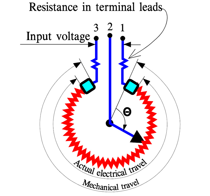
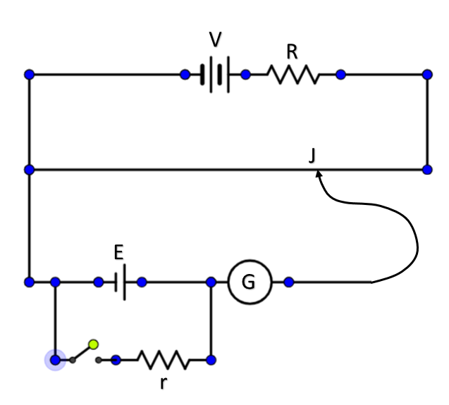
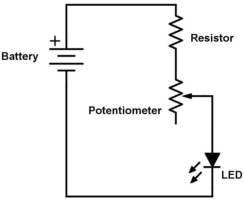
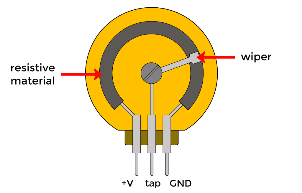
Potentiometer Drawing - How does a potentiometer work? Web today, potentiometers are much smaller and much more accurate than those early large and bulky variable resistances, and as with most electronic components, there are many different types and names ranging from variable resistor, preset, trimmer, rheostat and of course variable potentiometer. Potentiometer working can be explained when the potentiometer is understood. Web what is a potentiometer? Web this article will showcase use cases of potentiometers, as well as teach you how to connect and read data from them. A potentiometer has 3 pins. These versatile devices play a pivotal role in controlling and measuring electrical signals, providing a dynamic interface between circuits and the physical world they interact with. Two terminals (the blue and green) are connected to a resistive element and the third terminal (the black one) is connected to an adjustable wiper. Our potentiometers guide will help you understand their uses, how they work, the various types and characteristics. And also it is used to compare the emfs of different cells. Web potentiometers, or pots, are a type of resistor used to control the output signal on an electronic device, like a guitar, amplifier, or speaker. A complete guide to potentiometers. Web learn how to use a potentiometer with this tutorial covering a 10k potentiometer with its pin diagram, description and datasheet. Web in a circuit diagram, a potentiometer is represented by one of the two symbols below: And also it is used to compare the emfs of different cells. The purpose of a potentiometer circuit is to control the voltage level of an electronic signal. (a) shaft, (b) stationary carbon composition resistance element, (c) phosphor bronze wiper, (d) shaft attached to wiper, (e, g) terminals connected to ends of resistance element, (f) terminal connected to wiper. Web this is a potentiometer tutorial where you'll learn how it works and with examples of how potentiometers can be wired for various circuits. Topics covered in this guide. The potentiometer uses the comparative method which is more accurate than the deflection method. Potentiometer working can be explained when the potentiometer is understood. Web this is a potentiometer tutorial where you'll learn how it works and with examples of how potentiometers can be wired for various circuits. Web what is a potentiometer? One shows how you can use a potentiometer as an input for a color mixer, and the other shows how to accurately choose colors and how to smoothly fade between them. Web the known voltage is drawn by the cell or any other supply sources. “i rebuke you in the name of jesus,” she says in response. Web it is an electric component used to measure the unknown voltage by comparing it with the known one, which can be drawn by a cell or any of the other supply sources. This aims to address past challenges where people could cash out their full pension savings when changing jobs, leaving nothing for retirement. So, it is mostly used in the places where higher accuracy is required or where no current flows from the source under test. Web article continues below this ad. Web cutaway drawing of potentiometer showing parts: (a) shaft, (b) stationary carbon composition resistance element, (c) phosphor bronze wiper, (d) shaft attached to wiper, (e, g) terminals connected to ends of resistance element, (f) terminal connected to wiper. In other words, it is a device used for measuring the emf (electromotive force), and internal resistance of a given cell. Web. Web in this article, introduction to potentiometer wiring. One shows how you can use a potentiometer as an input for a color mixer, and the other shows how to accurately choose colors and how to smoothly fade between them. Web the potentiometer is an electric instrument used to measure the emf (electromotive force) of a given cell, the internal resistance. It allows partial withdrawals for emergencies while protecting most of the savings for retirement. Web what is a potentiometer? Web a beginner's tutorial on potentiometers. If a sensitive indicating instrument is used, very little current is drawn from the source of the unknown voltage. Web article continues below this ad. Web cutaway drawing of potentiometer showing parts: Web potentiometers, often referred to as pots, are fundamental components in the realm of electrical engineering. They have a small shaft on top that functions like a knob; Web it is an electric component used to measure the unknown voltage by comparing it with the known one, which can be drawn by a. Topics covered in this guide. Web a potentiometer (also known as a pot or potmeter) is defined as a 3 terminal variable resistor in which the resistance is manually varied to control the flow of electric current. Web a beginner's tutorial on potentiometers. In other words, it is a device used for measuring the emf (electromotive force), and internal resistance. Web a potentiometer is a variable resistor which works by changing resistance to adjust current or voltage, and the circuit diagram is used to illustrate how this is achieved. Web in a circuit diagram, a potentiometer is represented by one of the two symbols below: Web a potentiometer (also known as a pot or potmeter) is defined as a 3. The potentiometer uses the comparative method which is more accurate than the deflection method. “with a jackpot like that available, what an exciting time to be a mega millions player. When the user turns the shaft, it turns the resistance on the signal up or down. Understand how to use and select potentiometers. Web this article will showcase use cases. What’s the principle of a potentiometer? In other words, it is a device used for measuring the emf (electromotive force), and internal resistance of a given cell. Web a potentiometer is a variable resistor which works by changing resistance to adjust current or voltage, and the circuit diagram is used to illustrate how this is achieved. Understand how to use. Web what is a potentiometer? Web the known voltage is drawn by the cell or any other supply sources. How does a potentiometer work? When she grabs the pot of boiling water, one deputy steps back “away from your hot steaming water,” he says. It can also use as a variable resistor in most of applications. “i rebuke you in the name of jesus,” she says in response. One shows how you can use a potentiometer as an input for a color mixer, and the other shows how to accurately choose colors and how to smoothly fade between them. Web a potentiometer circuit diagram is a graphical representation of the components used in a potentiometer circuit,. These versatile devices play a pivotal role in controlling and measuring electrical signals, providing a dynamic interface between circuits and the physical world they interact with. Web a potentiometer circuit diagram is a graphical representation of the components used in a potentiometer circuit, such as resistors, transistors, and capacitors. Web this article will showcase use cases of potentiometers, as well as teach you how to connect and read data from them. Web a potentiometer is a variable resistor which works by changing resistance to adjust current or voltage, and the circuit diagram is used to illustrate how this is achieved. And also it is used to compare the emfs of different cells. Web in this article, introduction to potentiometer wiring. It allows partial withdrawals for emergencies while protecting most of the savings for retirement. On the left side, you’ll see the ground terminal, then the adjustable tap. “with a jackpot like that available, what an exciting time to be a mega millions player. Web a potentiometer schematic circuit diagram is a visual representation of the connections between the three terminals of the potentiometer. Understand how to use and select potentiometers. You will learn its symbol, construction, applications, potentiometer types, linear, log taper. What is the difference between potentiometer and voltmeter? This aims to address past challenges where people could cash out their full pension savings when changing jobs, leaving nothing for retirement. When the user turns the shaft, it turns the resistance on the signal up or down. What’s the principle of a potentiometer?Electronic Potentiometer Circuit Diagram
1/4" Smooth Shaft Potentiometer Right Angle PCB
[Proper] Potentiometer Connection and Circuit Diagram ETechnoG
Basic Principles of Potentiometers/Variable Resistors
Potentiometer Circuit Diagram And Working
Circuit Diagram Of A Potentiometer
(a) Annotated potentiometer schematic symbol. (b) Separation of the
Principle construction and working of potentiometer
How to Use Potentiometers on the Arduino Circuit Basics
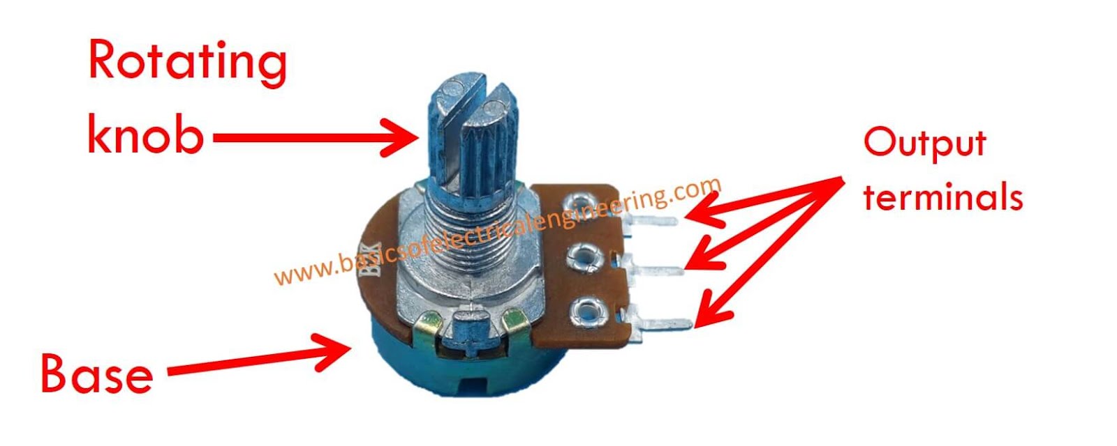
Basics of Potentiometer Basics of Electrical Engineering
Two Terminals (The Blue And Green) Are Connected To A Resistive Element And The Third Terminal (The Black One) Is Connected To An Adjustable Wiper.
Web The Known Voltage Is Drawn By The Cell Or Any Other Supply Sources.
They Have A Small Shaft On Top That Functions Like A Knob;
Web This Is A Potentiometer Tutorial Where You'll Learn How It Works And With Examples Of How Potentiometers Can Be Wired For Various Circuits.
Related Post:
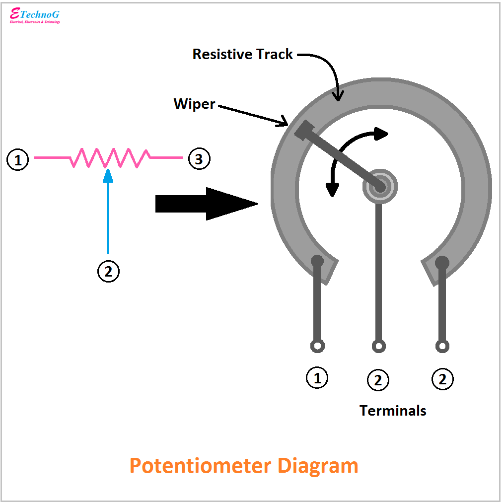

![[Proper] Potentiometer Connection and Circuit Diagram ETechnoG](https://3.bp.blogspot.com/-7pcmbMVljr8/XNV3lTwW0NI/AAAAAAAAB2A/3j9EWjEKIhkM-EN5eRJvIN2s6xnrr3bvACLcBGAs/s1600/Potentiometer%2Bterminals.png)
