Pump Drawing
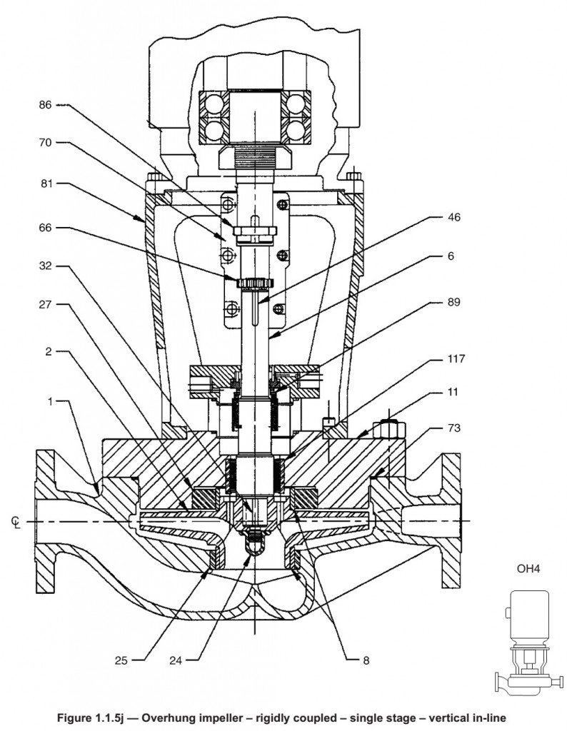
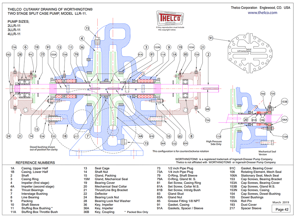
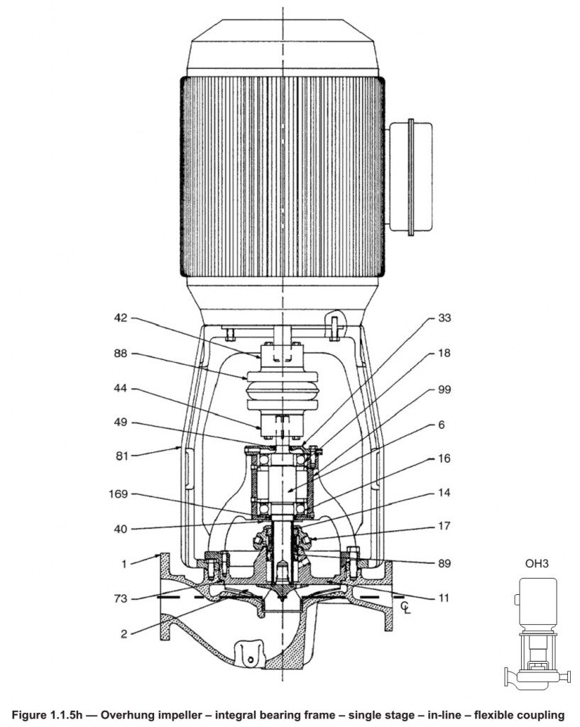
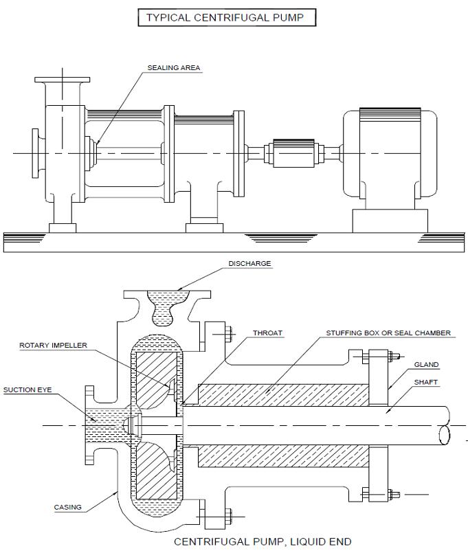
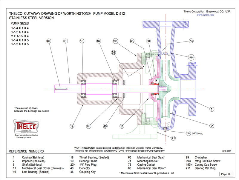
Pump Drawing - Web in this video, i am going to discuss the centrifugal pump diagram. His right fist is raised in the air and there is blood on his face. Web how to size an electric motor. Fluid enters the pump through the suction nozzle, into the eye of the impeller. Web positive displacement pumps force fluid out of the cavity through suction after drawing the fluid into the cavity or displacing the fluid. All pumps work by creating an area of. Different types of impellers and casings are combined to produce all of the different types of pumps. Web replica of a system with pumps and pipes. Web the paper starts with a brief explanation of pump operation including common pump faults and the main principles of the motor current signature analysis (mcsa) method. Web this schematic drawing of the centrifugal pump shows five different views of a pump. Obstructions include valves, elbows, “tees,” etc. V series pumps drawings 2. An impeller and a casing. Web a p&id is a drawing of a processing plan that entails the piping and process equipment with its instrumentation and control machinery. Web a pump schematic diagram is a technical drawing that illustrates the essential components and connections of a pump system. Web when you boil them down to the most fundamental components, pumps are made up of an impeller which creates velocity through rotation and a casing which converts velocity into pressure. Web w series pumps drawings. Web a pump schematic symbol is a graphical representation used in electrical and mechanical engineering diagrams to represent a pump. Web pumps are powered by means of several power sources, requiring manual operation, electricity, engine, wind power, and more. The fluid is drawn into centrifugal or aerodynamic pumps by a rotating impeller, which also accelerates the fluid’s exit from the pump’s outlet point. When designing an application, it can sometimes be difficult to get access to a 3d pump model. Web how to size an electric motor. Centrifugal pumps are made up of two primary components: 538 pumps cad blocks for free download dwg autocad, rvt revit, skp sketchup and other cad software. Keeping the pump suction piping short ensures that the inlet pressure drop is as low as possible. The two main parts of every centrifugal pump are the casing and the impeller. A us flag waves in the background in front of a blue sky. Keep suction piping as short as possible. P&id pump symbols— pumps can be used for suction, compression, moving fluid, and pressure control. His right fist is raised in the air and there is blood on his face. In this article, we will learn the basic definition, parts, types, how does centrifugal pump works, various diagrams, etc. 538 pumps cad blocks for free download dwg autocad, rvt revit, skp sketchup and other cad software. Kehoe’s campaign, meanwhile, had $1.2 million left after spending $1.1 million. It typically includes symbols and labels to clearly depict the pump, motor, valves,. Web explore our library of cutaway drawings of worthington® * pumps and flowserve® *pumps. Web p&id symbols for pumps. Fluid enters the pump through the suction nozzle, into the eye of the impeller. Web when you boil them down to the most fundamental components, pumps are made up of an impeller which creates velocity through rotation and a casing which. Web a pump schematic diagram is a technical drawing that illustrates the essential components and connections of a pump system. Web centrifugal pumps can be classified based on the manner in which fluid flows through the pump. The fan, identified as simha chalam, sought to draw attention to his personal issues and demanded a. Centrifugal pumps are made up of. The most important parts of a pump: An impeller and a casing. At grundfos product center, you can find and download pump drawings, including cad, quickly and easily. Here, flow and pressure are generated dynamically due to rotational energy. 2.1 foundation design and baseplate alignment. This section is comprised of both pumps and fans. All pumps work by creating an area of. Access technical data quickly and easily. Web p&id symbols for pumps. Centrifugal pumps are made up of two primary components: Different types of impellers and casings are combined to produce all of the different types of pumps. After reading this brief article, you’ll know where centrifugal pumps got their name and the basic forces that make a pump work. Here, flow and pressure are generated dynamically due to rotational energy. All pumps work by creating an area of. Web this. Keep suction piping as short as possible. P&id pump symbols— pumps can be used for suction, compression, moving fluid, and pressure control. Web evan vucci's photographs depict donald trump moments after an assassination attempt. W series pumps drawings 2. Web the paper starts with a brief explanation of pump operation including common pump faults and the main principles of the. 1.2 pump receiving and inspection. P&id pump symbols— pumps can be used for suction, compression, moving fluid, and pressure control. W series pumps drawings 2. These drawings are useful in identifying the thelco part for your pump needs as well as supporting our customers with on the ground installations. Web the paper starts with a brief explanation of pump operation. P&id pump symbols— pumps can be used for suction, compression, moving fluid, and pressure control. Web explore our library of cutaway drawings of worthington® * pumps and flowserve® *pumps. 1.2 pump receiving and inspection. Web positive displacement pumps force fluid out of the cavity through suction after drawing the fluid into the cavity or displacing the fluid. It typically includes. Access technical data quickly and easily. V series pumps drawings 2. In this view, you can see the pump’s internal parts, such as the impeller, impeller eye, packing, shaft, etc. All pumps work by creating an area of. Web explore our library of cutaway drawings of worthington® * pumps and flowserve® *pumps. When designing an application, it can sometimes be difficult to get access to a 3d pump model. Here, flow and pressure are generated dynamically due to rotational energy. The rotating impeller generates velocity and the casing converts velocity into flow. Download flow charts and drawings for the williams v and w series pumps. Web p&id symbols for pumps. What is a centrifugal pump? In this article, we will learn the basic definition, parts, types, how does centrifugal pump works, various diagrams, etc. A us flag waves in the background in front of a blue sky. Web this schematic drawing of the centrifugal pump shows five different views of a pump. Web a pump schematic symbol is a graphical representation used in electrical and mechanical engineering diagrams to represent a pump. 538 pumps cad blocks for free download dwg autocad, rvt revit, skp sketchup and other cad software. Access technical data quickly and easily. These drawings are useful in identifying the thelco part for your pump needs as well as supporting our customers with on the ground installations. This section is comprised of both pumps and fans. Web a p&id is a drawing of a processing plan that entails the piping and process equipment with its instrumentation and control machinery. It is a standardized symbol that allows engineers and technicians to quickly identify and understand the presence and function of a pump in a given system.Pump Drawing at GetDrawings Free download
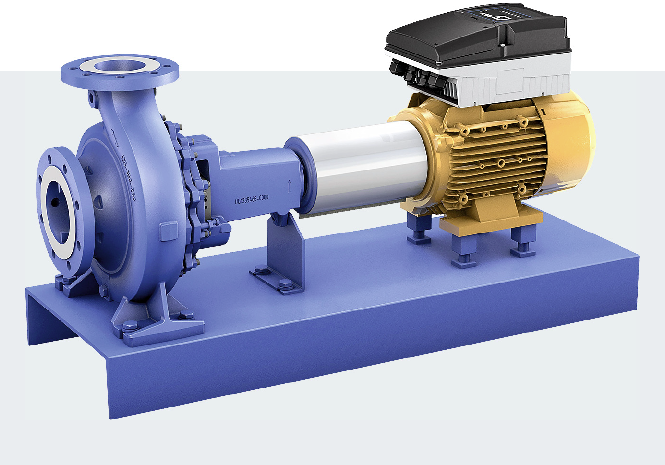
Ksb pump drawings
Pump Technical Drawings Thelco Corporation
Pump Drawing at GetDrawings Free download
Pump Drawing at Explore collection of Pump Drawing
Ksb pump drawings
Pump Technical Drawings Thelco Corporation
Pump Drawing at Explore collection of Pump Drawing
Ksb pump drawings
Pump Technical Drawings Thelco Corporation
His Joint Fundraising Pac, Committee For Liberty, Had $58,833 After Spending $1 Million.
Web A Pump Schematic Diagram Is A Technical Drawing That Illustrates The Essential Components And Connections Of A Pump System.
Typically, Pumps Work By A Vacuum In Which Air Pressure Forces The Liquid Out.
Web When You Boil Them Down To The Most Fundamental Components, Pumps Are Made Up Of An Impeller Which Creates Velocity Through Rotation And A Casing Which Converts Velocity Into Pressure.
Related Post:
