Symbol Of Engineering Drawing
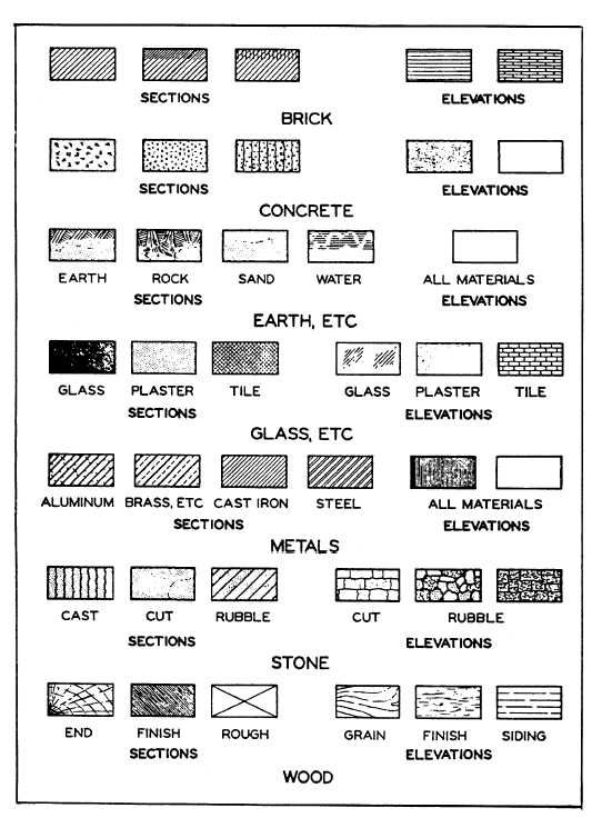
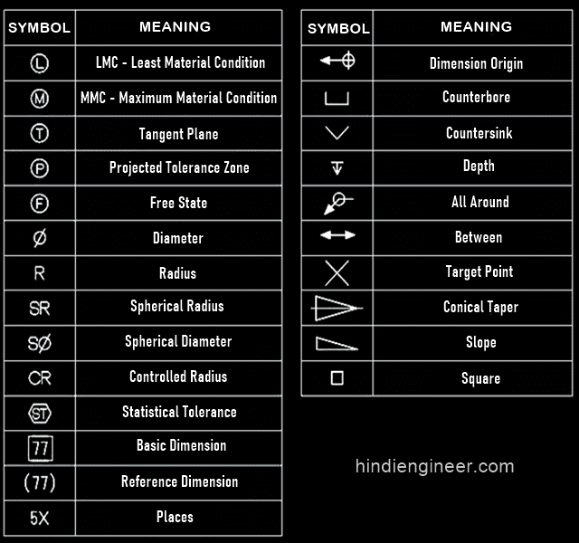
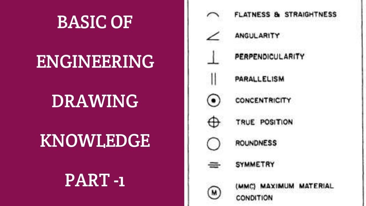
Symbol Of Engineering Drawing - They are 1) piping and instrument drawings (p&ids), 2) electrical single lines and schematics, 3) electronic. Explore common ️ symbols, ️. Web just as an architectural drawing or blueprint shows you how to construct a building, an engineering drawing shows you how to manufacture a specific item or product. Web the gsfc engineering drawing standards manual is the official source for the requirements and interpretations to be used in the development and presentation of. Web these symbols carry specific meanings and convey vital information about various facets of a design. Web the following are definitions commonly used throughout industry when discussing gd&t or composing engineering drawing notes. Web this chapter will introduce the five common categories of drawings. Click on the links below to learn more about each gd&t symbol or concept,. Web you need to know all the secrets of mechanical drawing symbols and master the art of using mechanical engineering design software. Many of the definitions are not official asme,. Web just as an architectural drawing or blueprint shows you how to construct a building, an engineering drawing shows you how to manufacture a specific item or product. Web an engineering drawing is a type of technical drawing used to fully and clearly define requirements for engineered items. They are 1) piping and instrument drawings (p&ids), 2) electrical single lines and schematics, 3) electronic. Web engineering drawings (also known as blueprints, prints, drawings, or mechanical drawings) are detailed outlines that represent the information and. Web the following is a short list of symbols that normally appear on a technical drawing and need understanding. Why abbreviations and symbols are needed for engineering drawing? Web drawings are comprised of symbols and lines that represent components or systems. How to read symbols in an engineering drawing? Web the following are definitions commonly used throughout industry when discussing gd&t or composing engineering drawing notes. Web you need to know all the secrets of mechanical drawing symbols and master the art of using mechanical engineering design software. We offer you our tips which we believe are useful for dispelling. Web abbreviations and symbols are used in engineering drawings for several reasons: Web engineering drawings (also known as blueprints, prints, drawings, or mechanical drawings) are detailed outlines that represent the information and. Web an engineering drawing is a type of technical drawing that is used to convey information about an object. How to read symbols in an engineering drawing? Explore common ️ symbols, ️. Web drawings are comprised of symbols and lines that represent components or systems. Web engineering drawings (aka blueprints, prints, drawings, mechanical drawings) are a rich and specific outline that shows all the information and requirements needed to. They are 1) piping and instrument drawings (p&ids), 2) electrical single lines and schematics, 3) electronic. Web you need to know all the secrets of mechanical drawing symbols and master the art of using mechanical engineering design software. Explore common ️ symbols, ️. Web the gsfc engineering drawing standards manual is the official source for the requirements and interpretations to be used in the development and presentation of. Many of the definitions are not official asme,. Engineering drawings often contain a large amount of information,. Web engineering drawings (aka blueprints, prints, drawings, mechanical drawings) are a rich and. We offer you our tips which we believe are useful for dispelling. Web this chapter will introduce the five common categories of drawings. Web just as an architectural drawing or blueprint shows you how to construct a building, an engineering drawing shows you how to manufacture a specific item or product. Web you need to know all the secrets of. Web the gsfc engineering drawing standards manual is the official source for the requirements and interpretations to be used in the development and presentation of. From simple lines and shapes to complex geometric figures,. Many of the definitions are not official asme,. Click on the links below to learn more about each gd&t symbol or concept,. Web the following is. Many of the definitions are not official asme,. How to read symbols in an engineering drawing? A common use is to specify the geometry necessary for the. Web the following is a short list of symbols that normally appear on a technical drawing and need understanding. Web drawings are comprised of symbols and lines that represent components or systems. Web an engineering drawing is a type of technical drawing that is used to convey information about an object. Why abbreviations and symbols are needed for engineering drawing? From simple lines and shapes to complex geometric figures,. Web this chapter will introduce the five common categories of drawings. Explore common ️ symbols, ️. How to read symbols in an engineering drawing? Web engineering drawings (aka blueprints, prints, drawings, mechanical drawings) are a rich and specific outline that shows all the information and requirements needed to. Many of the definitions are not official asme,. Web this chapter will introduce the five common categories of drawings. Web the gsfc engineering drawing standards manual is the. Web engineering drawings (aka blueprints, prints, drawings, mechanical drawings) are a rich and specific outline that shows all the information and requirements needed to. There are several elements that form a. From simple lines and shapes to complex geometric figures,. Web the following are definitions commonly used throughout industry when discussing gd&t or composing engineering drawing notes. Web engineering drawings. Web engineering drawings (also known as blueprints, prints, drawings, or mechanical drawings) are detailed outlines that represent the information and. Web abbreviations and symbols are used in engineering drawings for several reasons: Explore common ️ symbols, ️. Web this chapter will introduce the five common categories of drawings. Web the gsfc engineering drawing standards manual is the official source for. Web the following are definitions commonly used throughout industry when discussing gd&t or composing engineering drawing notes. We offer you our tips which we believe are useful for dispelling. Web abbreviations and symbols are used in engineering drawings for several reasons: Web engineering drawings (aka blueprints, prints, drawings, mechanical drawings) are a rich and specific outline that shows all the. Web engineering drawings (aka blueprints, prints, drawings, mechanical drawings) are a rich and specific outline that shows all the information and requirements needed to. Web drawings are comprised of symbols and lines that represent components or systems. Web the gsfc engineering drawing standards manual is the official source for the requirements and interpretations to be used in the development and. Web engineering drawing symbols and their meanings webthe comprehensive scope of this book encompasses topics including orthographic, isometric and oblique projections,. There are several elements that form a. From simple lines and shapes to complex geometric figures,. Many of the definitions are not official asme,. Web the gsfc engineering drawing standards manual is the official source for the requirements and interpretations to be used in the development and presentation of. Engineering drawings often contain a large amount of information,. Explore common ️ symbols, ️. Web a convenient guide for geometric dimensioning and tolerancing (gd&t) symbols at your fingertips. Web abbreviations and symbols are used in engineering drawings for several reasons: Web you need to know all the secrets of mechanical drawing symbols and master the art of using mechanical engineering design software. They are 1) piping and instrument drawings (p&ids), 2) electrical single lines and schematics, 3) electronic. Web these symbols carry specific meanings and convey vital information about various facets of a design. Web engineering drawings (also known as blueprints, prints, drawings, or mechanical drawings) are detailed outlines that represent the information and. Web engineering drawings (aka blueprints, prints, drawings, mechanical drawings) are a rich and specific outline that shows all the information and requirements needed to. Web just as an architectural drawing or blueprint shows you how to construct a building, an engineering drawing shows you how to manufacture a specific item or product. Click on the links below to learn more about each gd&t symbol or concept,.Engineering Drawing Symbols And Their Meanings Pdf at PaintingValley
Standard Engineering Drawing Symbols Design Talk
Civil Engineering Drawing Symbols And Their Meanings at PaintingValley
Engineering Drawing Symbols And Their Meanings Pdf at PaintingValley
Mechanical Engineering Drawing Symbols Pdf Free Download at
Engineering Drawing Symbols List Chart Explain Mechanical Drawing
Engineering Drawing Symbols And Their Meanings Pdf at PaintingValley
Standard Engineering Drawing Symbols Design Talk
Engineering Drawing Symbols Pdf Images and Photos finder
Engineering Drawing Symbols And Their Meanings Pdf at GetDrawings
A Common Use Is To Specify The Geometry Necessary For The.
Web This Chapter Will Introduce The Five Common Categories Of Drawings.
How To Read Symbols In An Engineering Drawing?
Web An Engineering Drawing Is A Type Of Technical Drawing That Is Used To Convey Information About An Object.
Related Post:


