What Is A Pid Drawing
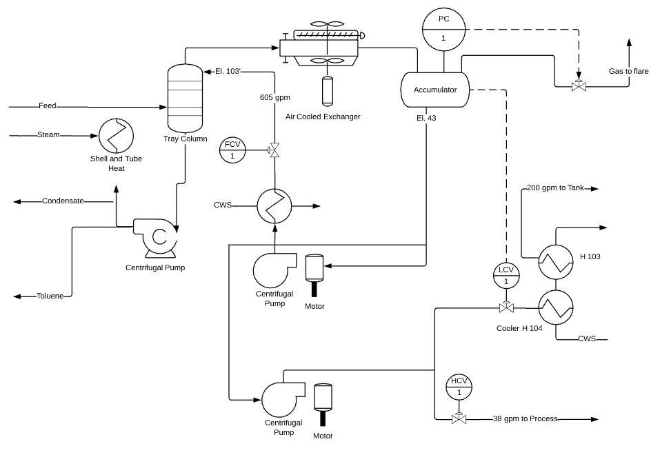
What Is A Pid Drawing - Web a p&id or process and instrumentation diagram provides a detailed graphical representation of the actual process system that includes the piping, equipment, valves,. A p&id uses simple graphics to represent complex processes and convey the. Web a piping and instrumentation diagram, or p&id, shows the piping and related components of a physical process flow. Here you can find what information is contained on a p&id. P&id is short for “piping and instrumentation diagram”. It represents all details of the chemical process at. Web piping and instrumentation diagram (p&id) is a schematic representation of a process flow between all process units or equipment's in a plant. Web what should a piping and instrumentation (p&id) drawing include? Web piping and instrumentation diagram examples. It’s most commonly used in the engineering field. Here you can find what information is contained on a p&id. Web stephen's glasses draw comparisons to clark kent following his performance on the pommel horse, fans immediately began to call stephen the clark kent of the. Web p&id (piping and instrumentation diagram or drawing) is a technical drawing used in process engineering. Web a piping and instrumentation diagram, or p&id, shows the piping and related components of a physical process flow. It’s most commonly used in the engineering field. Web piping and instrumentation diagram examples. As shown in the p&id, ft 501 is a field mounted flow transmitter connected via electrical signals (dotted lines) to a flow indicator and controller, fic 501. P&id is short for “piping and instrumentation diagram”. Web p&id symbols and notation. P&ids can be manually drawn or in a digital format. It’s most commonly used in the engineering field. As shown in the p&id, ft 501 is a field mounted flow transmitter connected via electrical signals (dotted lines) to a flow indicator and controller, fic 501. Web what should a piping and instrumentation (p&id) drawing include? Web p&id stands for the piping and instrumentation diagram. With download pdf for free. Web it is used to identify hazardous areas classification, and preparing data sheets of equipment, valves, and instrument. Web a p&id is an important engineering document that shows the interconnection of process equipment and instrumentation to control the design system. Web a p&id or process and instrumentation diagram provides a detailed graphical representation of the actual process system that includes the piping, equipment, valves,. Web p&id stands for piping and instrumentation diagram. it is a very important industrial diagram representing the exact working of the processes in an industrial plant. Pid and p&id are totally different things! As shown in the p&id, ft 501 is a field mounted flow transmitter connected via electrical signals (dotted lines) to a flow indicator and controller, fic 501. Web piping and instrumentation diagram (p&id) is a schematic representation of a process flow between all process units or equipment's in a plant. It’s most commonly used in the engineering field. Web p&id. Since there is only one pipe on the bottom, it has an. Web it is used to identify hazardous areas classification, and preparing data sheets of equipment, valves, and instrument. As shown in the p&id, ft 501 is a field mounted flow transmitter connected via electrical signals (dotted lines) to a flow indicator and controller, fic 501. There's a huge. What is a piping and instrumentation diagram? Web piping and instrumentation diagram (p&id) is a drawing elaborating the details of piping and instrumentation of a processing plant, developed at the design stage. Web a piping and instrumentation diagram (p&id) is a comprehensive schematic that illustrates the functional relationship of piping, instrumentation, and system equipment components. Web what should a piping. Web piping and instrumentation diagram examples. Pid stands for proportional, integral, and derivative which are parameters used in algorithms for controlling the. Web a p&id is an important engineering document that shows the interconnection of process equipment and instrumentation to control the design system. Like other specialized diagrams, p&id's are comprised of standard shapes and symbols. Web p&id stands for. P&id is used to develop the piping layout and. Web a piping and instrumentation diagram (p&id) is a comprehensive schematic that illustrates the functional relationship of piping, instrumentation, and system equipment components. Web stephen's glasses draw comparisons to clark kent following his performance on the pommel horse, fans immediately began to call stephen the clark kent of the. Web how. Pid stands for proportional, integral, and derivative which are parameters used in algorithms for controlling the. Pid and p&id are totally different things! Web a p&id or process and instrumentation diagram provides a detailed graphical representation of the actual process system that includes the piping, equipment, valves,. Web a piping and instrumentation diagram, or p&id, shows the piping and related. Web a p&id is an important engineering document that shows the interconnection of process equipment and instrumentation to control the design system. It represents all details of the chemical process at. Web stephen's glasses draw comparisons to clark kent following his performance on the pommel horse, fans immediately began to call stephen the clark kent of the. Web it is. Web the lines representing pipes on the top of the tank indicate whether the fluid is going into or out of the tank. A p&id uses simple graphics to represent complex processes and convey the. It’s most commonly used in the engineering field. Pid stands for proportional, integral, and derivative which are parameters used in algorithms for controlling the. Web. Web a piping and instrumentation diagram, or p&id, shows the piping and related components of a physical process flow. With download pdf for free. Web p&id symbols and notation. Web p&id (piping and instrumentation diagram or drawing) is a technical drawing used in process engineering. P&ids can be manually drawn or in a digital format. Web the lines representing pipes on the top of the tank indicate whether the fluid is going into or out of the tank. Web piping and instrumentation diagram (p&id) is a drawing elaborating the details of piping and instrumentation of a processing plant, developed at the design stage. Web piping and instrumentation diagram examples. A p&id uses simple graphics to. Web what should a piping and instrumentation (p&id) drawing include? It’s most commonly used in the engineering field. Web a piping and instrumentation diagram (p&id) is a comprehensive schematic that illustrates the functional relationship of piping, instrumentation, and system equipment components. As shown in the p&id, ft 501 is a field mounted flow transmitter connected via electrical signals (dotted lines) to a flow indicator and controller, fic 501. Web how to draw a piping & instrumentation diagram? Both formats commonly contain information. Web piping and instrumentation diagram (p&id) is a schematic representation of a process flow between all process units or equipment's in a plant. P&id is used to develop the piping layout and. Web it is used to identify hazardous areas classification, and preparing data sheets of equipment, valves, and instrument. Pid and p&id are totally different things! A piping and instrumentation diagram, also called p&id, is a. Web p&id (piping and instrumentation diagram or drawing) is a technical drawing used in process engineering. What is a piping and instrumentation diagram? Web piping and instrumentation diagram examples. Web p&id stands for piping and instrumentation diagram. it is a very important industrial diagram representing the exact working of the processes in an industrial plant. Like other specialized diagrams, p&id's are comprised of standard shapes and symbols.What is a P&ID Beginner’s Guide EdrawMax Online
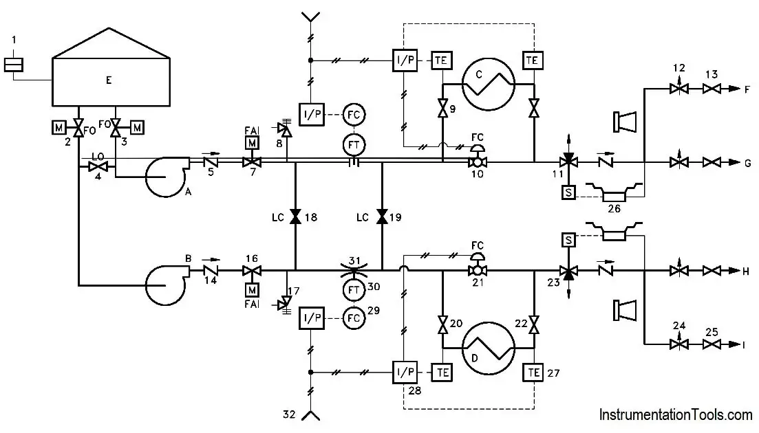
Piping and Instrumentation Documents Instrumentation Tools
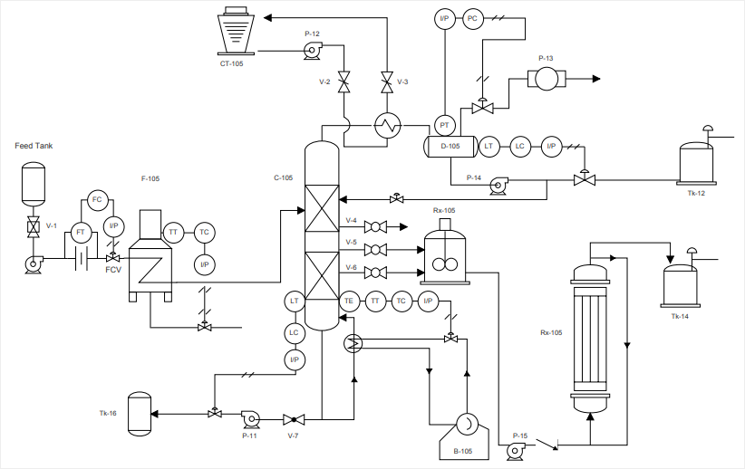
How to Read a P&ID Drawing Quickly and Easily Edraw Max
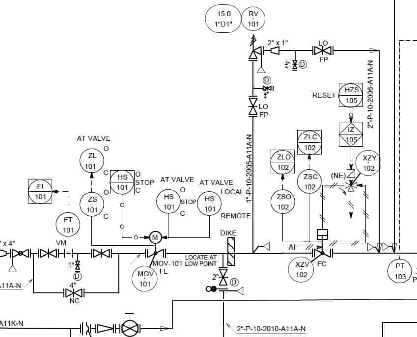
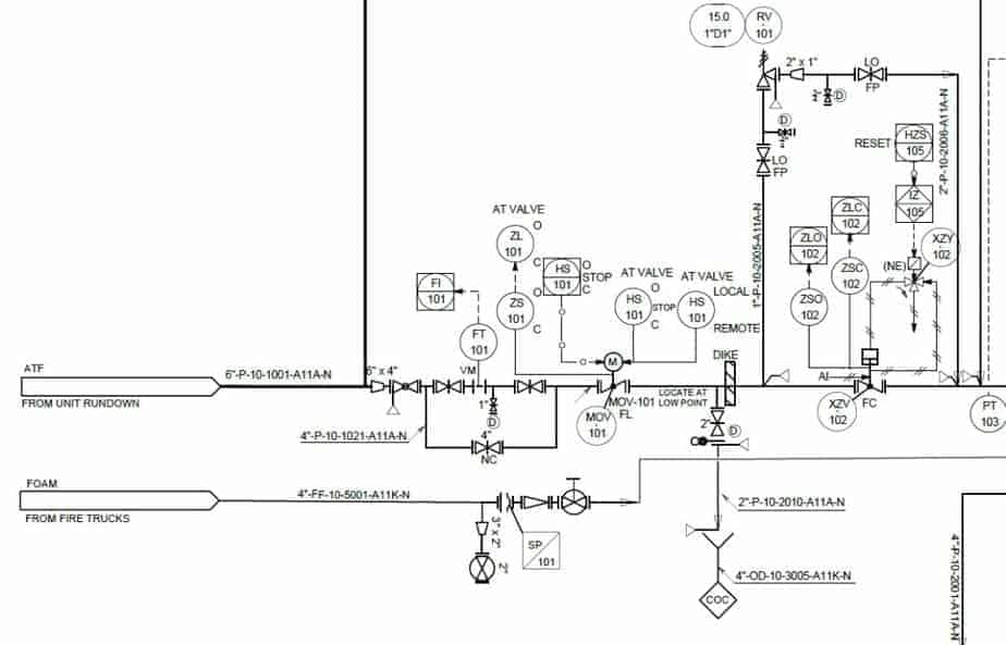
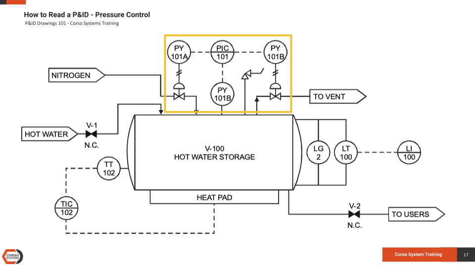
P&ID Drawings 201 Reading Real World Examples — Corso Systems
P & ID Diagram. How To Read P&ID Drawing Easily. Piping
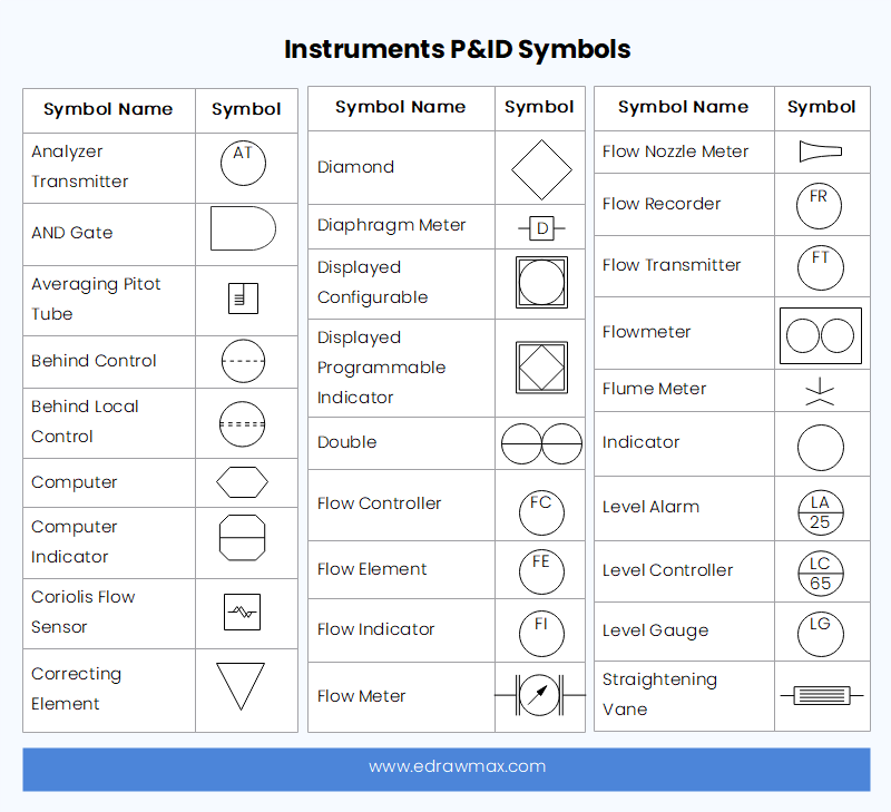
P&id Schematic Symbols
Learn How to Read P&ID Drawings A Complete Guide
Learn How to Read P&ID Drawings A Complete Guide
What is a P&ID Beginner’s Guide EdrawMax Online
Learn How to Read P&ID Drawings A Complete Guide
Since There Is Only One Pipe On The Bottom, It Has An.
Web Piping And Instrumentation Diagram (P&Id) Is A Drawing Elaborating The Details Of Piping And Instrumentation Of A Processing Plant, Developed At The Design Stage.
Web A Piping And Instrumentation Diagram, Or P&Id, Shows The Piping And Related Components Of A Physical Process Flow.
Here You Can Find What Information Is Contained On A P&Id.
Related Post:
.png)


