Which Architectural Drawings Show The Side View Of A Building
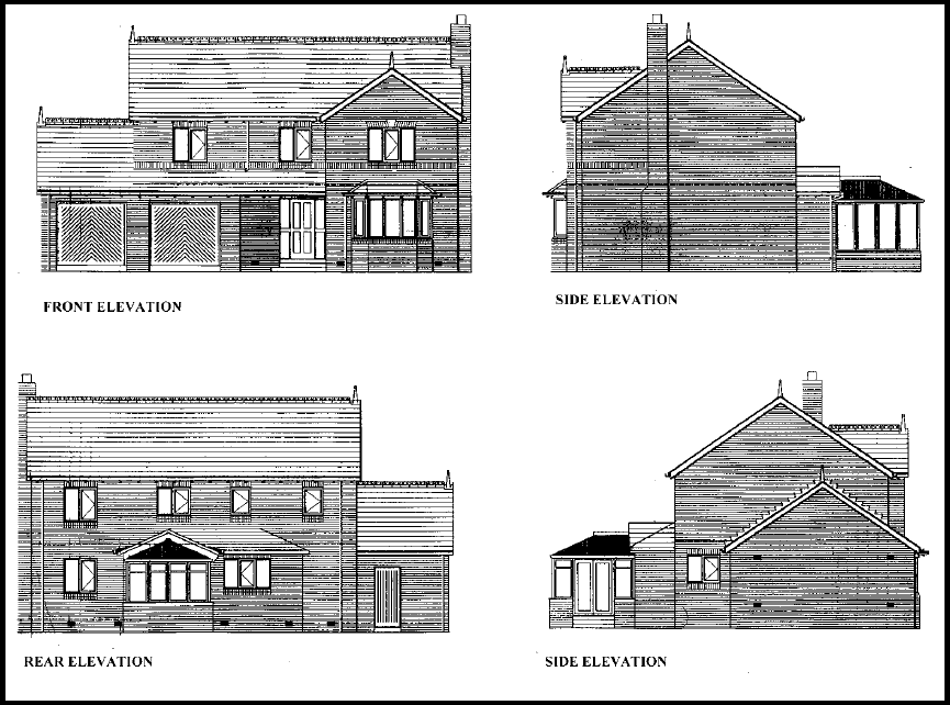
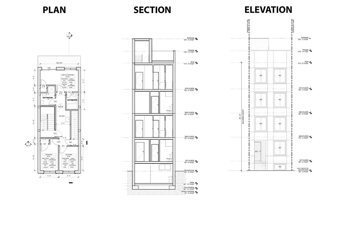
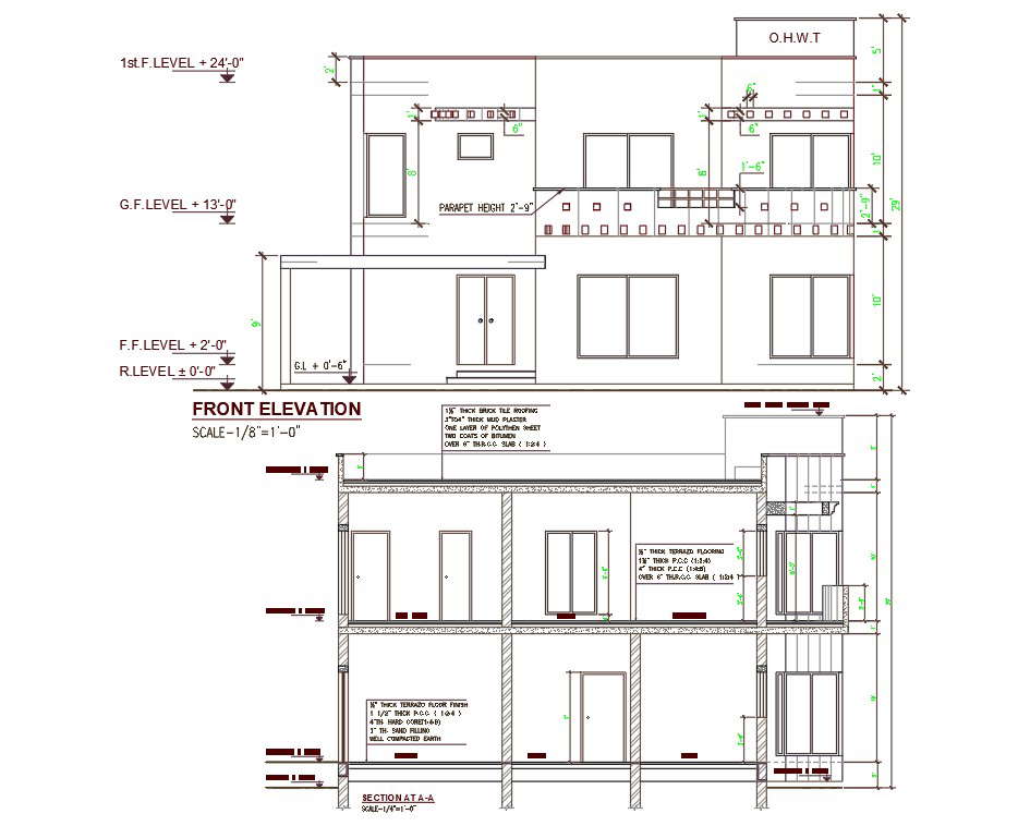
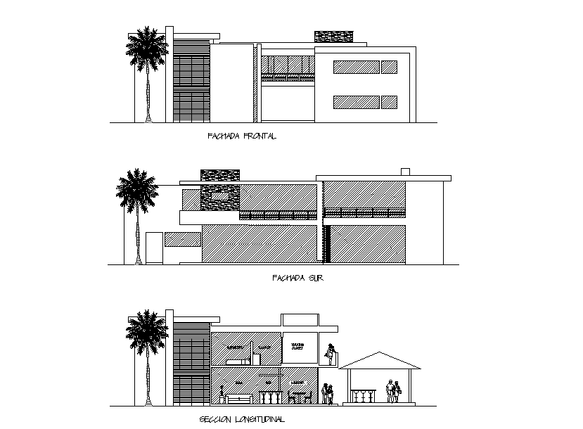
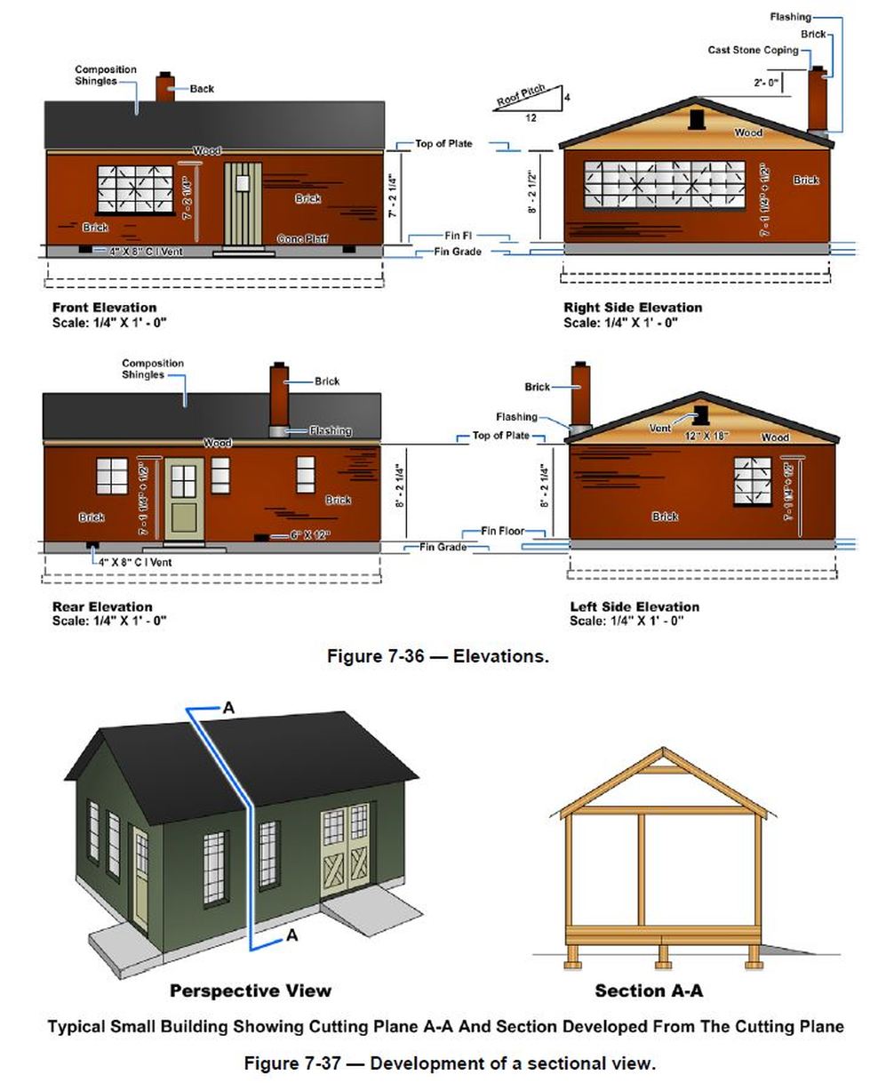
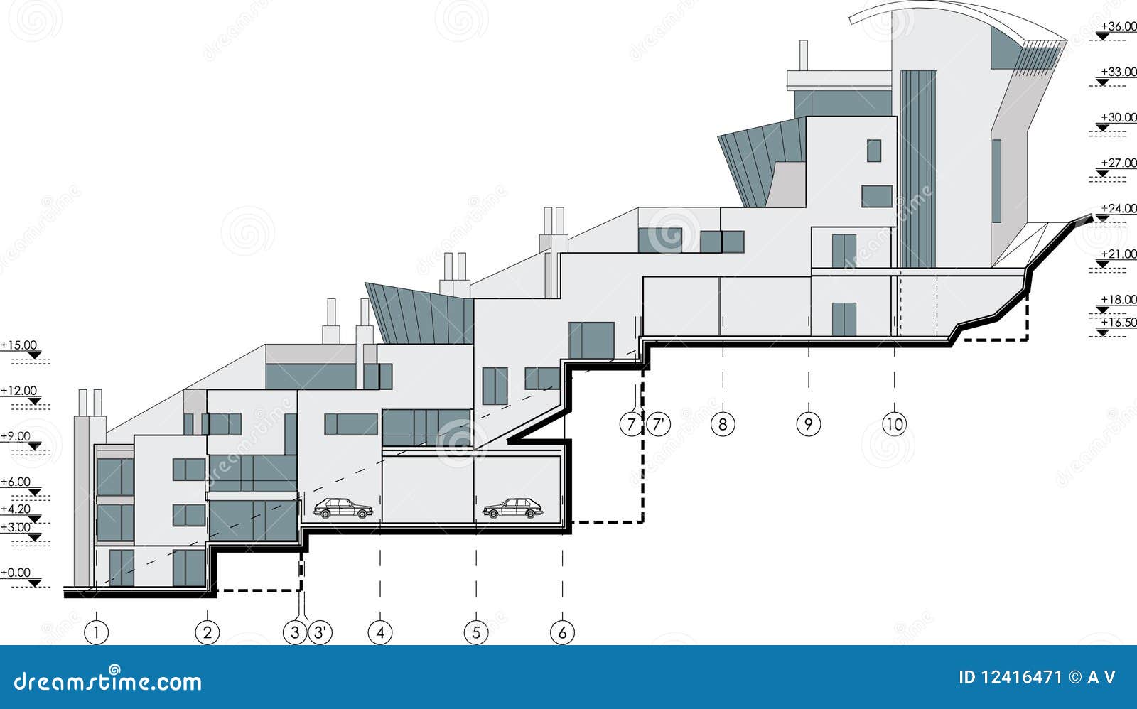
Which Architectural Drawings Show The Side View Of A Building - The two main types of views (or “projections”) used in drawings are: These are the drawings that communicate what the. It can be taken in multiple positions and in multiple directions. Usually the architect selects a position that will reveal most about the vertical relationships in the building: Web these are views from the exterior, indicating the material used in exterior walls, (brick, stucco, vinyl, etc), the location of windows and doors from a side view, the roof slopes, and other elements visible from the exterior. These are crucial for assessing the flow between different building levels and are extensively used to plan mepf systems and other internal components. Web height drawings of objects are called front and side views. Other architectural plans are cut horizontally through the building or object, usually at a height of about 1200mm above the ground or a floor plane. Web an elevation drawing looks at a building’s vertical side, rather than looking up or down as in a plan. A section drawing is also a vertical depiction. This is the most common view used to describe the external appearance of a building. These are crucial for assessing the flow between different building levels and are extensively used to plan mepf systems and other internal components. It communicates heights, floor levels, windows, trim work, materials, and the overall character of the building. Web an elevation is a view of a building seen from one side, a flat representation of one façade. Web these drawings detail the structural components of a building, such as beams, columns, foundations, and roofs, including materials, sizes, and connections. Site plans are important for showing exactly how the structure is positioned concerning the property boundaries. Web height drawings of objects are called front and side views. This is the most common view used to describe the external appearance of a building. Other architectural plans are cut horizontally through the building or object, usually at a height of about 1200mm above the ground or a floor plane. Inside the mind of the architect. Structural drawings are critical for ensuring the building’s stability and safety, complementing the architectural drawings with technical engineering information. They usually show the exterior sides of a house or building and include details like architectural features, the placement and style of doors and windows, and information about building materials or. Usually the architect selects a position that will reveal most about the vertical relationships in the building: A section drawing is also a vertical depiction. You can also use these drawings to see window and door details, siding details, and gutter locations A section is a vertical cut through the building. Web in a standard set of architectural plans on a small residential project, the elevations will most likely be a set of drawings from the main facades of the building. An elevation drawing is drawn on a vertical plane showing a vertical depiction. Web these drawings detail the structural components of a building, such as beams, columns, foundations, and roofs, including materials, sizes, and connections. This is the most common view used to describe the external appearance of a building. The site plan provides an aerial view of the building and its surrounding property. These orthographic projections lay out a structure’s external appearance, usually as a flat depiction of one façade. An elevation is a vertical view of an object projected onto a picture plane. Web _____ drawing show the side view of a building or object showing height and. Other architectural plans are cut horizontally through the building or object, usually at a height of about 1200mm above the ground or a floor plane. It reveals how things are built, highlighting the main structural parts and the materials used that give the project its unique character. You can also use these drawings to see window and door details, siding. They usually show the exterior sides of a house or building and include details like architectural features, the placement and style of doors and windows, and information about building materials or. Web _____ drawing show the side view of a building or object showing height and width. Web sign up to receive future program updates > architectural elevations are a. Site plans are important for showing exactly how the structure is positioned concerning the property boundaries. Sometimes it’ll even show neighboring buildings or infrastructure like roads. The two main types of views (or “projections”) used in drawings are: Web in architectural drawing, this is known as a top view or top plan. Usually the architect selects a position that will. Elevation from zen apartments, kingscliff this is the most common view used to describe the external appearance of a building. These drawings are close to how we will physically encounter a building as we walk through it, though they make no accounting for the viewer’s perspective. The most common construction plans are site plans, plot plans, foundation plans, floor plans,. An elevation drawing is drawn on a vertical plane showing a vertical depiction. Web elevation plans are most typically drawn to show the exterior façade of a building. The site plan provides an aerial view of the building and its surrounding property. A standard section view cuts straight through a building or object to show what's inside. An elevation is. These drawings are close to how we will physically encounter a building as we walk through it, though they make no accounting for the viewer’s perspective. Web in short an architectural elevation is a drawing of an interior or exterior vertical surface or plane, that forms the skin of the building. Types of views used in drawings. Other architectural plans. Web sign up to receive future program updates > architectural elevations are a classic mode of communication for architects, the third in a tripartite along with plans and section drawings. Other architectural plans are cut horizontally through the building or object, usually at a height of about 1200mm above the ground or a floor plane. Elevation from zen apartments, kingscliff. This is the most common view used to describe the external appearance of a building. Web it’s usually done to show the exterior of the building as seen from the front, back and side. Web plan, section, and elevation are different types of drawings used by architects to graphically represent a building design and construction. Both types of drawings use. These are the drawings that communicate what the. Looking toward the north you would be seeing the southern elevation of the building. Web in short an architectural elevation is a drawing of an interior or exterior vertical surface or plane, that forms the skin of the building. Web these are views from the exterior, indicating the material used in exterior. Web an elevation drawing looks at a building’s vertical side, rather than looking up or down as in a plan. It communicates heights, floor levels, windows, trim work, materials, and the overall character of the building. Types of views used in drawings. Web in short an architectural elevation is a drawing of an interior or exterior vertical surface or plane, that forms the skin of the building. A section drawing is also a vertical depiction. Web in a standard set of architectural plans on a small residential project, the elevations will most likely be a set of drawings from the main facades of the building. Usually the architect selects a position that will reveal most about the vertical relationships in the building: Site plans are important for showing exactly how the structure is positioned concerning the property boundaries. The site plan provides an aerial view of the building and its surrounding property. An elevation is a vertical view of an object projected onto a picture plane. Sometimes it’ll even show neighboring buildings or infrastructure like roads. Other architectural plans are cut horizontally through the building or object, usually at a height of about 1200mm above the ground or a floor plane. You can also use these drawings to see window and door details, siding details, and gutter locations A section is a vertical cut through the building. Elevation from zen apartments, kingscliff this is the most common view used to describe the external appearance of a building. These orthographic projections lay out a structure’s external appearance, usually as a flat depiction of one façade.Architectural Cross Section Drawing Southbank Centre Work
Drafting Standards for Interior Elevations Construction Drawings
Types of drawings for building design Designing Buildings Wiki
Plan, Section, Elevation Architectural Drawings Explained · Fontan
AutoCAD 2d CAD drawing of architecture double story house building
Modern House Building Front And Side View Sectional Elevation Drawing
An Architectural Drawing Of The Right Side Elevation vrogue.co
ARCHITECTURAL CONSTRUCTION DRAWINGS
The Cabin Project Technical Drawings Life of an Architect
Side Facade Building Drawing Stock Illustration Illustration of
It Reveals How Things Are Built, Highlighting The Main Structural Parts And The Materials Used That Give The Project Its Unique Character.
An Elevation Drawing Is Drawn On A Vertical Plane Showing A Vertical Depiction.
The Two Main Types Of Views (Or “Projections”) Used In Drawings Are:
It Can Be Taken In Multiple Positions And In Multiple Directions.
Related Post:


