Break Lines In Engineering Drawing
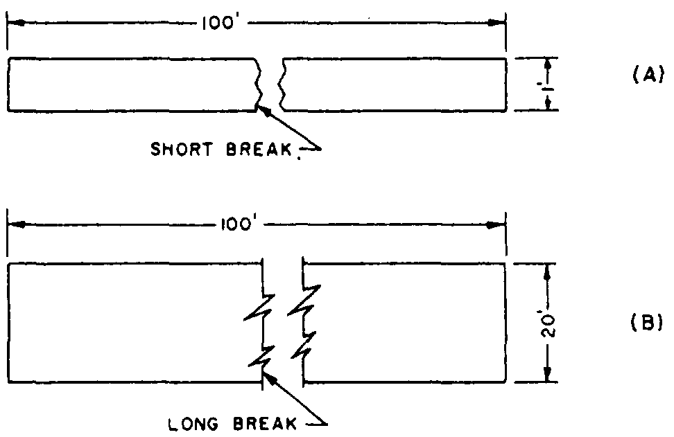
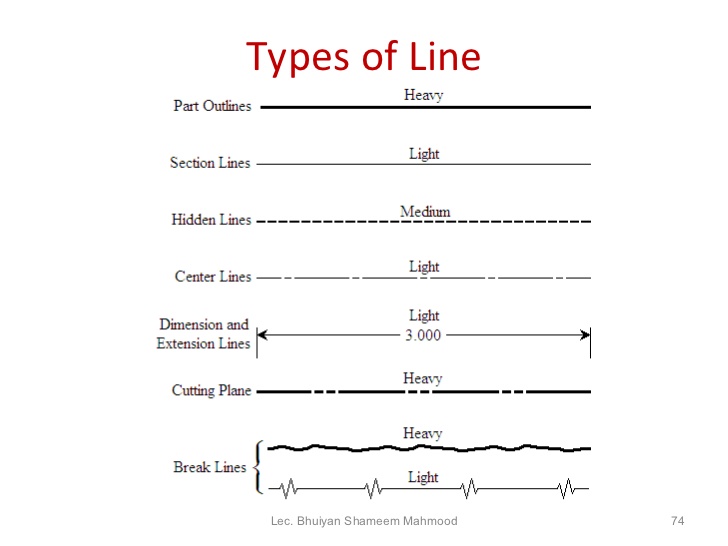
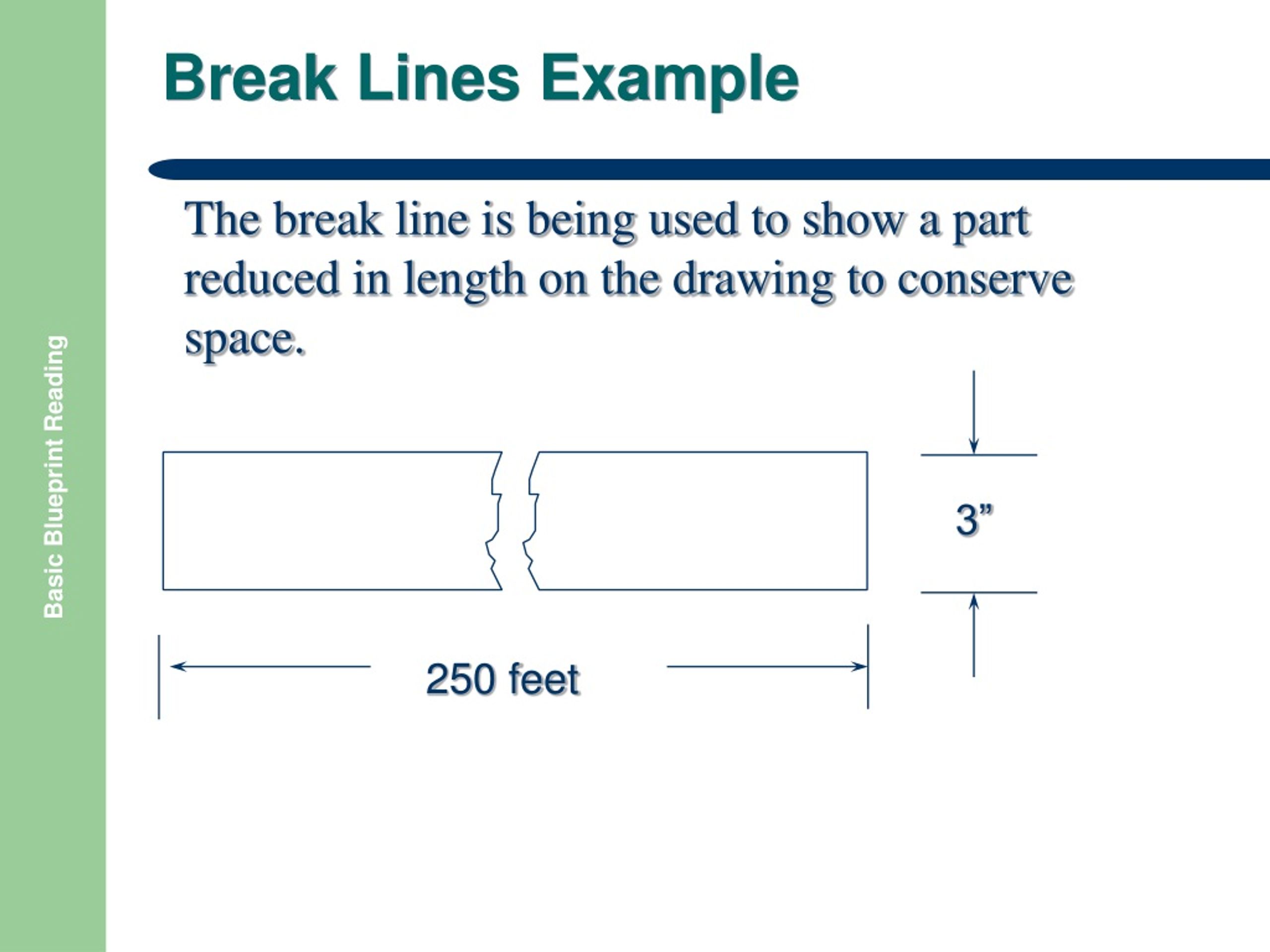
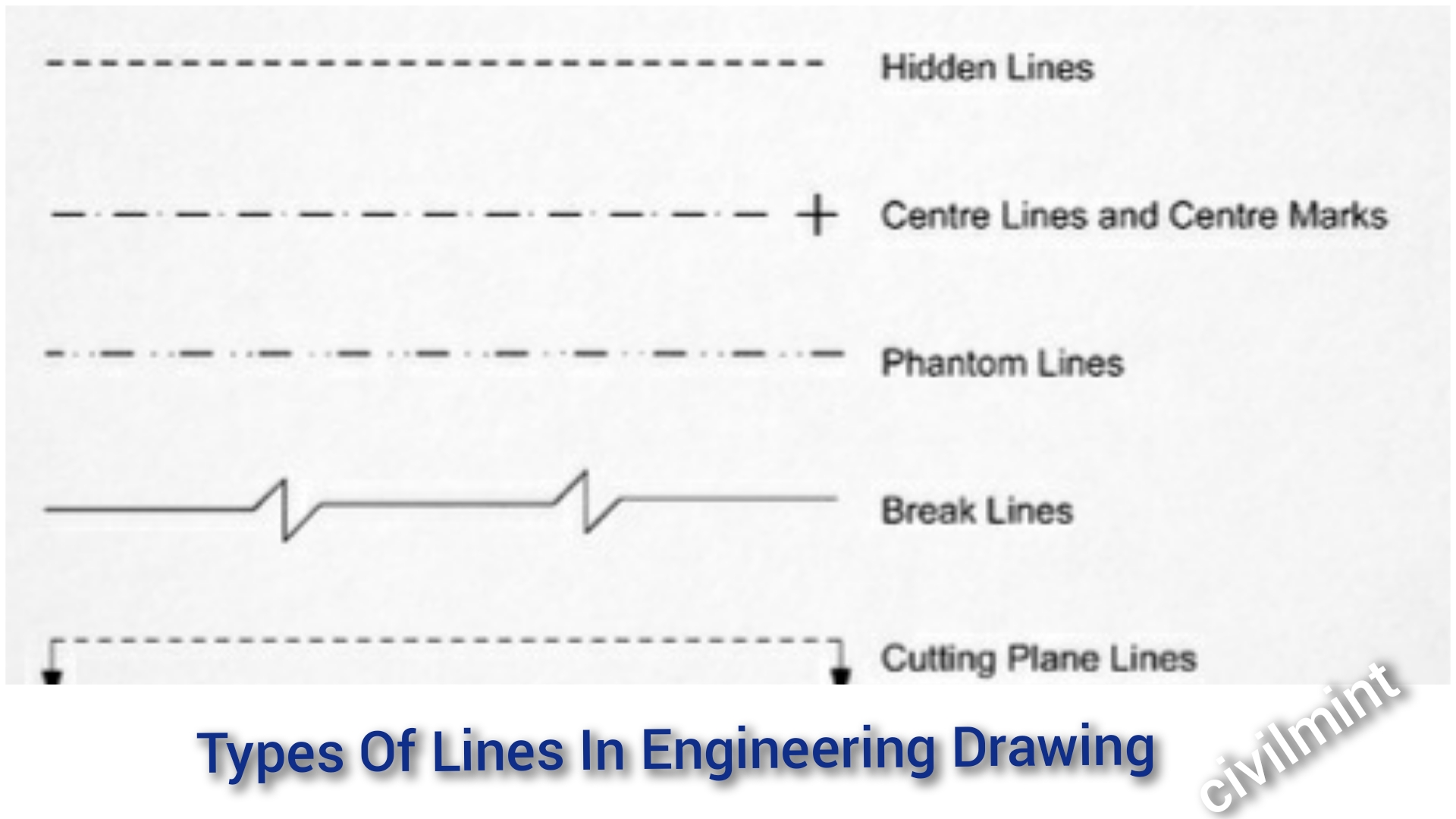
Break Lines In Engineering Drawing - Usually the first lines that you will use on a drawing are construction lines. The two variations of break lines common to blueprints are the long break line and the short break line (figure 11). Continuous, hidden, center and phantom. Civil engineers draw plans for bridges and road layouts. Long break lines are thin solid lines that have zigzags to indicate a break. Web engineering lines are graphical representations used in technical drawings to communicate information about the shape, size, and features of objects. The standard recommends using, no less than, two line widths. Break lines are drawn to show that a part has been shortened to reduce its size on the drawing. Web there are three kinds of break lines used in drawings. They are used to remove, or ‘break out” part of a drawing for clarity, and also to shorten objects which have the same shape throughout their length and may be too long to place on the drawing. Web break lines are the type of technical drawing line that is used to create breakouts on sections in order to shorten distances between parts of a drawing and give more clarity. The standard recommends using, no less than, two line widths. Mechanical engineers draw parts and assemblies that need to be manufactured. Radius of an arc is to be indicated, there is an arrow at only the end of the line that touches the arc. These lines act as a language that engineers and designers understand to visualize and convey complex ideas accurately. Short break lines are denoted by a thick wavy line and are used to break the edge or surface of a part to reveal a concealed surface. If a part needs to be shortened with a break for ease of visibility, a break can be made using this line. Break lines are used to represent a long or continuous object or feature that is too large to be shown in its entirety on a drawing. Three types of lines are normally used as break lines; Thin lines when compared with the thick lines are. Usually the first lines that you will use on a drawing are construction lines. Civil engineers draw plans for bridges and road layouts. Web an engineering drawing is a visual representation that communicates the design, dimensions, and specifications of an object or assembly. Break lines come in two forms: They consist of zigzag or squiggly lines that indicate where the object has been “broken” for clarity. There are three types of break lines, each with a distinct line weight: The other end, without an arrow, terminates at the point used as the center in drawing the arc. In those cases, we have very powerful tools available to us. Web the continuous thin zigzag line shows a break line. Dimension and extension lines are used to indicate the sizes of features on a drawing. Thin lines when compared with the thick lines are. Long break lines, short break lines, and cylindrical break lines. Web break lines are the type of technical drawing line that is used to create breakouts on sections in order to shorten distances between parts of a drawing and give more clarity. The standard recommends using, no less than, two line. Common thicknesses are 0.6 mm for important lines and 0.3 mm for the less important lines. Web werk24's ai automatically reads the break lines from technical drawings, determines whether a dimension is out of scale, and confirms the break line perspective. Hidden lined (thick) hidden lined (thick) type lines consist of thick short dashes, closely and evenly spaced. Mechanical engineers. In those cases, we have very powerful tools available to us. Web an engineering drawing is a visual representation that communicates the design, dimensions, and specifications of an object or assembly. Web there are four commonly used line types: That is, the length is roughly three times the width. Short break lines are denoted by a thick wavy line and. These lines are drawn to represent hidden or invisible edges of the objects. Break lines are used to represent a long object or feature that is too large to be shown in its entirety on a drawing. Mechanical engineers draw parts and assemblies that need to be manufactured. Hidden lined (thick) hidden lined (thick) type lines consist of thick short. Break lines are used to represent a long object or feature that is too large to be shown in its entirety on a drawing. Hidden lined (thick) hidden lined (thick) type lines consist of thick short dashes, closely and evenly spaced. They are used to remove, or ‘break out” part of a drawing for clarity, and also to shorten objects. Web there are four commonly used line types: For example, electrical engineers draw circuit schematics and circuit board layouts. A freehand thick line, and a long, ruled thin line with zigzags. Common thicknesses are 0.6 mm for important lines and 0.3 mm for the less important lines. They will also be used to lay out the rest of your drawing. In those cases, we have very powerful tools available to us. Web long break lines are most commonly used to indicate where a part of the drawing was removed or not drawn in its entirety. They consist of zigzag or squiggly lines that indicate where the object has been “broken” for clarity. The other end, without an arrow, terminates at. Web line characteristics, such as widths, breaks in the line, and zigzags, all have definite meanings. Break lines are used to represent a long object or feature that is too large to be shown in its entirety on a drawing. Important lines should be twice as thick as the less important thin lines. Web in introduction to engineering drawings, we. Break lines are used to represent a long object or feature that is too large to be shown in its entirety on a drawing. The two variations of break lines common to blueprints are the long break line and the short break line (figure \(\pageindex{11}\)). *remember, any dimensions spanning over the break needs to have a dimension break indicated on. A freehand thick line, and a long, ruled thin line with zigzags. Web certain lines in the drawing are drawn very thick so that they clearly bear other unique form of information on the drawing. They consist of zigzag or squiggly lines that indicate where the object has been “broken” for clarity. Dimension and extension lines are used to indicate. Web there are four commonly used line types: In those cases, we have very powerful tools available to us. Long break lines, short break lines, and cylindrical break lines. Web line characteristics, such as widths, breaks in the line, and zigzags, all have definite meanings. Break lines are drawn to show that a part has been shortened to reduce its size on the drawing. Web certain lines in the drawing are drawn very thick so that they clearly bear other unique form of information on the drawing. Web break lines in engineering drawings are very important and are used to separate sections for clarity or to shorten a section. Web the continuous thin zigzag line shows a break line. Sometimes using main orthographic views is impossible to show all the features of an object to the degree that the object is sufficiently described for manufacturing. Web engineering drawings come in many forms. The two variations of break lines common to blueprints are the long break line and the short break line (figure \(\pageindex{11}\)). Break lines are used to represent a long object or feature that is too large to be shown in its entirety on a drawing. They consist of zigzag or squiggly lines that indicate where the object has been “broken” for clarity. Three types of lines are normally used as break lines; By kelly curran glenn sokolowski. Web long break lines are most commonly used to indicate where a part of the drawing was removed or not drawn in its entirety.Werk24 Understands the Break Lines from Technical Drawings
DRAWING BASICS
How to draw a break line
Break Lines In Technical Drawing
Engineering Drawing 8 Tips to Improve Engineering Drawing Skills
Engineering Drawing 2 Ch4 Conventional break YouTube
Classifications of Civil Engineering Drawings and Interpreting
PPT BASIC BLUEPRINT READING PowerPoint Presentation, free download
Types Of Lines In Engineering Drawing
Line Conventions
These Lines Are Drawn To Represent Hidden Or Invisible Edges Of The Objects.
They Have Different Line Weights:
Dimension And Extension Lines Are Used To Indicate The Sizes Of Features On A Drawing.
Web Werk24'S Ai Automatically Reads The Break Lines From Technical Drawings, Determines Whether A Dimension Is Out Of Scale, And Confirms The Break Line Perspective.
Related Post:
.png?format=1500w)


