Symbol Mechanical Drawing
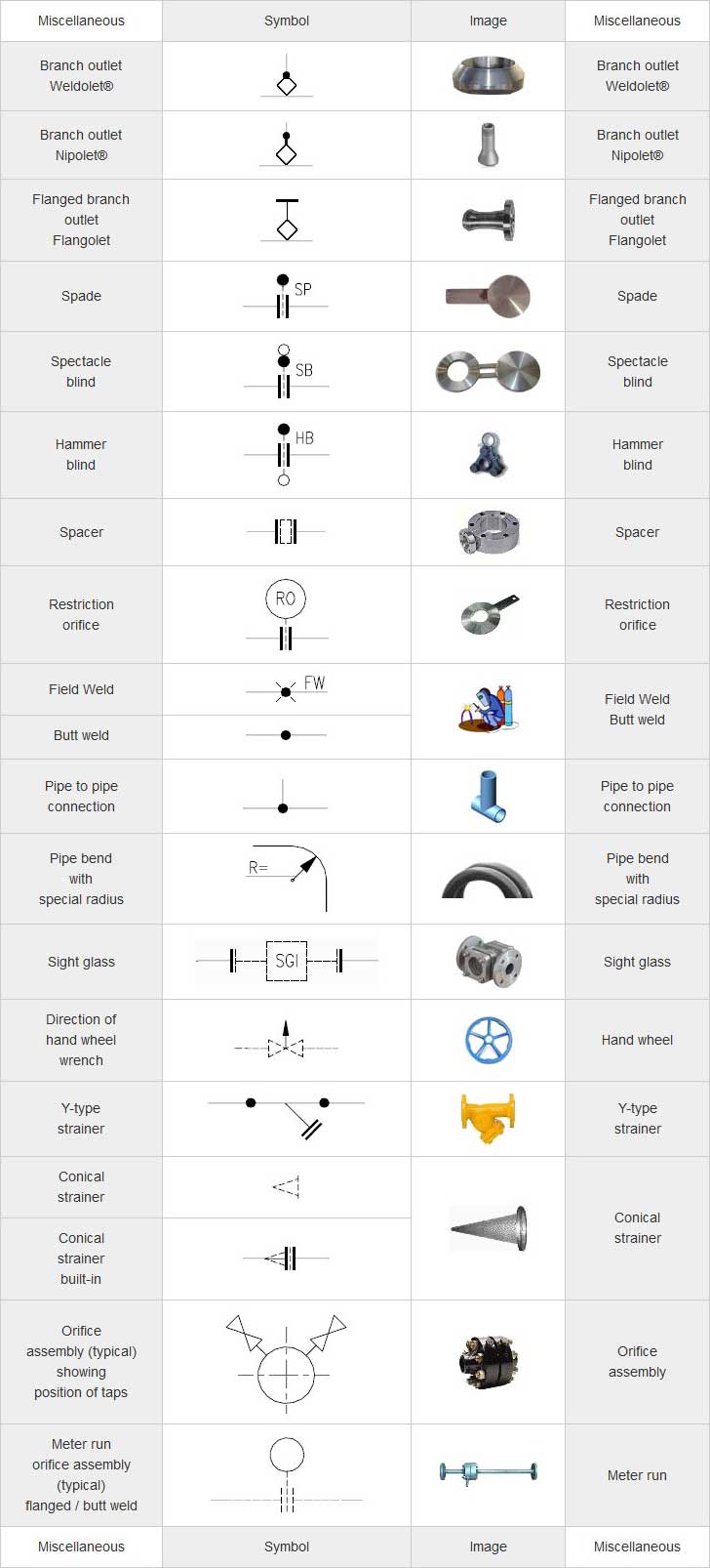
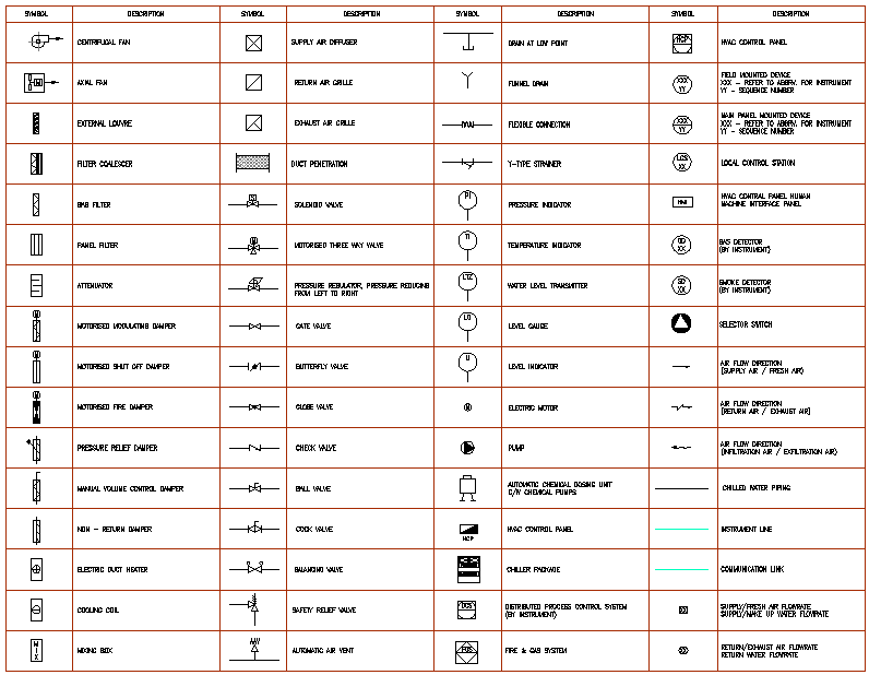
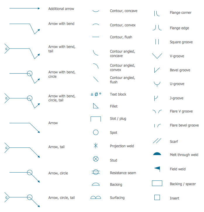
Symbol Mechanical Drawing - Web mechanical drawing symbols are standardized graphical representations used on blueprints to indicate the geometry and function of items within a system. Engineering drawings often contain a large amount of information, including dimensions, tolerances, annotations, and other details. You can also check out the gd&t symbols and terms on our site. These icons are essential for creating an accurate visual language. Click to download or update adobe acrobat ® now. Web find common gd&t symbols in convenient charts broken down by their use in drawing and drafting. Web mechanical drawing symbols are used to represent components and processes in diagrams. There's a huge variety of symbols, depending on industry and manufacturer, so we've created this guide to feature the most popular p&id symbols supported within our p&id software and is standardized for best practice across the. Identify the commonly use drawing representation used in the electrotechnology industry. Web engineering drawing abbreviations and symbols are used to communicate and detail the characteristics of an engineering drawing. Web drafting symbols symbols provide a “common language” for drafters all over the world. Here are more commonly used engineering drawing symbols and design elements as below. However, symbols can be meaningful only if they are created according to the relevant standards or conventions. Unlike a model, engineering drawings offer more specific detail and requirements, such as: Web mechanical drawing symbols are standardized graphical representations used on blueprints to indicate the geometry and function of items within a system. These icons are essential for creating an accurate visual language. Web various symbols and abbreviations in engineering drawings give you information about the dimensions, design, and materials used. Frames shall be circular and shall incorporate a seating gasket; Web find common gd&t symbols in convenient charts broken down by their use in drawing and drafting. This document describes and illustrates common dimensioning, gd&t, architectural, piping, and electrical symbols. Like other specialized diagrams, p&id's are comprised of standard shapes and symbols. This list includes abbreviations common to the vocabulary of people who work with engineering drawings in the manufacture and inspection of parts and assemblies. The basic symbol for the pump is a circle containing one or more arrow heads indicating the direction(s) of flow with the points of the arrows in contact with the circle. Engineering drawings often contain a large amount of information, including dimensions, tolerances, annotations, and other details. Web if you don't have autocad® software and wish to view the drawings, you can download autodesk's dwg true view program. The flange shall incorporate bedding slots and bolt holes. Familiarize yourself with common symbols, such as geometric tolerancing symbols, surface finish symbols, and welding symbols, among others. These icons are essential for creating. Click to download or update adobe acrobat ® now. Web annotations and symbols on a mechanical drawing provide additional information about features, materials, processes, and special considerations. Web the following is a short list of symbols that normally appear on a technical drawing and need understanding. Web explain the meaning of basic abbreviations and symbols used in drawing of mechanical components. Frames shall be circular and shall incorporate a seating gasket; Web in this post, we’ll go over the basics of how to read engineering drawing symbols.. Web our custom engineering drawing and blueprint printing services will save you time and money while making your design look as precise and professional as possible. Web engineering standards manual 6 5th edition section 8.09 medians. Web mechanical drawing symbols are used to represent components and processes in diagrams. These symbols can include lines, boxes, circles, arcs and text. Radius. Web in the broad area of fluid power, two categories of pump symbols are used, depending on the motive media being used (i.e., hydraulic or pneumatic). 1 west chambers medical center (super clinic) civil engineer: Web there was also a risk in drafting a high school pitcher in the first round for the second consecutive year. Frames shall be circular. Web annotations and symbols on a mechanical drawing provide additional information about features, materials, processes, and special considerations. 1 west chambers medical center (super clinic) civil engineer: Web mechanical drawing symbols are standardized graphical representations used on blueprints to indicate the geometry and function of items within a system. Ala hijazi engineering working drawings basics page 7 of 22. Web. Here are more commonly used engineering drawing symbols and design elements as below. This list includes abbreviations common to the vocabulary of people who work with engineering drawings in the manufacture and inspection of parts and assemblies. Lay out a drawing of mechanical components using engineering drawing convention. There's a huge variety of symbols, depending on industry and manufacturer, so. Using abbreviations and symbols allows for concise representation, making the drawings easier to read and understand. Radius can be for the inside and outside curved surface on the part. Web there was also a risk in drafting a high school pitcher in the first round for the second consecutive year. These symbols can include lines, boxes, circles, arcs and text.. We offer you our tips which we believe are useful for dispelling uncertainty by comparing the symbol with its graphic representation. Click to download or update adobe acrobat ® now. Lay out a drawing of mechanical components using engineering drawing convention. Web drawing name project issues / revisions consultants print date / time: The flange shall incorporate bedding slots and. This list includes abbreviations common to the vocabulary of people who work with engineering drawings in the manufacture and inspection of parts and assemblies. 1 west chambers medical center (super clinic) civil engineer: The basic symbol for the pump is a circle containing one or more arrow heads indicating the direction(s) of flow with the points of the arrows in. Like other specialized diagrams, p&id's are comprised of standard shapes and symbols. The flange shall incorporate bedding slots and bolt holes. Web mechanical drawing symbols are standardized graphical representations used on blueprints to indicate the geometry and function of items within a system. This list includes abbreviations common to the vocabulary of people who work with engineering drawings in the. Web find common gd&t symbols in convenient charts broken down by their use in drawing and drafting. Using abbreviations and symbols allows for concise representation, making the drawings easier to read and understand. [1] these symbols and abbreviations are standardized by the american national standards institute (asmi) and the american society of mechanical engineers (asme) in the us. You can. Frame depth shall not exceed 4. The flange shall incorporate bedding slots and bolt holes. Frames shall be circular and shall incorporate a seating gasket; Web there was also a risk in drafting a high school pitcher in the first round for the second consecutive year. Like other specialized diagrams, p&id's are comprised of standard shapes and symbols. How to read an engineering drawing symbol. Web engineering standards manual 6 5th edition section 8.09 medians. However, symbols can be meaningful only if they are created according to the relevant standards or conventions. Unlike a model, engineering drawings offer more specific detail and requirements, such as: Engineering drawings often contain a large amount of information, including dimensions, tolerances, annotations, and other details. The basic symbol for the pump is a circle containing one or more arrow heads indicating the direction(s) of flow with the points of the arrows in contact with the circle. Brown & gay engineers, inc. Click to download or update adobe acrobat ® now. Here are more commonly used engineering drawing symbols and design elements as below. Web drawing name project issues / revisions consultants print date / time: Web explain the meaning of basic abbreviations and symbols used in drawing of mechanical components.Mechanical Engineering Drawing Symbols Pdf Free Download at
Mechanical Engineering Drawing Symbols Pdf Free Download at
Mechanical Drawing Symbols Process Flow Diagram Symbols Electrical
how to read mechanical engineering drawing symbols Wiring Work
Mechanical Engineering Symbols Cadbull
Mechanical Engineering Solution
Mechanical Drawing Symbols
Mechanical Engineering Drawing Symbols Pdf Free Download at
Standard Engineering Drawing Symbols Design Talk
Mechanical Drawing Symbols
Web Basic Types Of Symbols Used In Engineering Drawings Are Countersink, Counterbore, Spotface, Depth, Radius, And Diameter.
You Can Also Check Out The Gd&T Symbols And Terms On Our Site.
These Icons Are Essential For Creating An Accurate Visual Language.
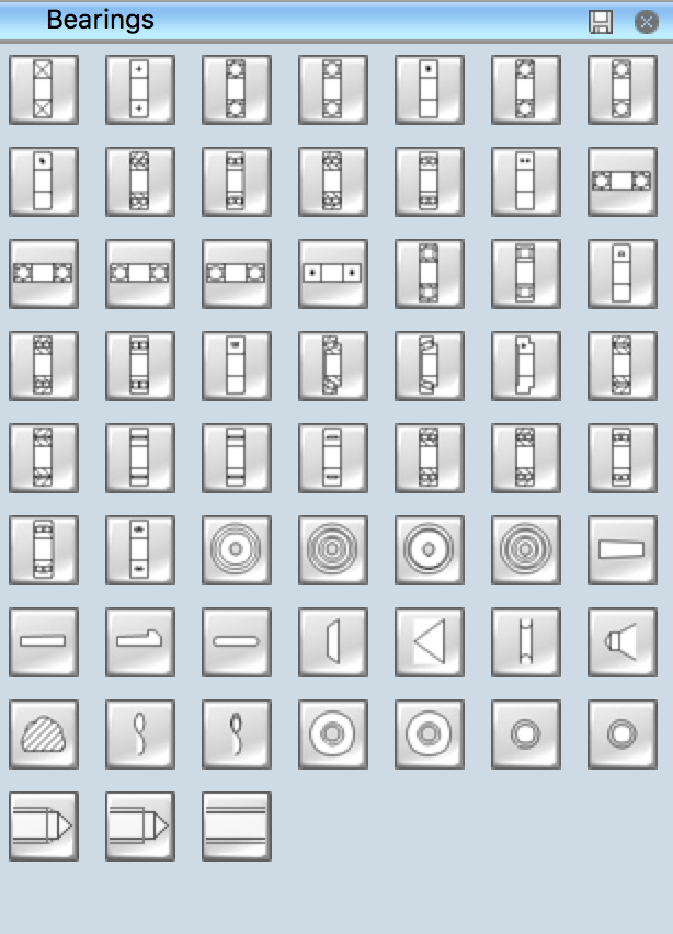
Web The Included Collection Of Predesigned Mechanical Drafting Symbols, Machining Drawing Symbols, And Machinist Symbols Helps In Drawing Mechanical Diagrams And Schematics, Mechanical Drafting Symbols Chart Or Mechanical Drawing Quickly, Easily, And Effectively.
Related Post:


